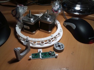
I managed to convince myself that pursuing my pan/tilt design was a good idea. The design itself is complete and I have sourced all the parts I need. Some parts have already started arriving.
If you don’t know what I’m talking about, or would like to fit the parts described below to the design then you can find the details here.
The parts from Shapeways arrived today. Shapeways is a 3D printing service, an activity I had hoped to achieve with my ill-fated RepRap. I’ll fix it one day… Anywho! Shapeways prints much finer things than a RepRap is capable of and offers a few more choices of material.
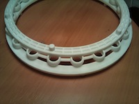 The big white circle is the bearing that the whole pan/tilt mount sits on. It takes the weight while still allowing it to rotate. Given it’s relatively large diameter, it should keep everything stable.
The top and bottom part mate with the steel base plate and the main chassis while providing a groove for some steel balls to roll in. The middle is a spacer to keep the balls evenly spaced.
The whole mechanism is held by a central bolt which clamps the two halves together against this bearing.
This is Shapeways laser sintered plastic. It can be pretty strong if you don’t make it too thin. I’m very happy with the accuracy of the print. Remind me to go back and tighten the tolerances in my design.
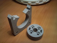 The squareish part on the left here is a motor brace. It fits between one of the motors and the chassis to allow space for gears to turn.
I made the decision to place the ’tilt’ gears inside the chassis rather than on the outside face. This is for a few minor reasons including aesthetic, symmetry and safety. This way both outside faces are flush and there are no exposed gear teeth to byte hapless fingers.
The round part is a locking hub, supposed to bolt to the face of a panel and lock it to a shaft with two set-screws.
This kind of part is surprisingly difficult to find for a reasonable price and in the right size. I managed to find some imperial sized bits that are ‘close enough’ from ServoCity. This printed version is just in case I can’t use the steel ones.
Both of these are printed in alumide; a combination of the plastic above and aluminium powder. Not quite as strong as the plastic but much harder. The motor brace will work fine but I am skeptical about the locking hub. Fingers crossed those ServoCity hubs are suitable.
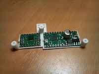 The last piece I’ve ordered from Shapeways is a PCB bracket. This bolts onto the chassis and holds the controller PCBs for the pan/tilt mount.
I may have made this a little bit too skinny. It was one of those situations where it looked fine in CAD on my computer and I failed to realise just how small it really was.
This one successfully holds the PCBs but it does do so under some tension. I think it’ll be fine to make the prototype work, but I’ll probably replace it with a sturdier version at some point.
The actual PCBs I’m using are pretty straight forward stepper controllers from Little Bird. Thanks to Madeline at Little Bird for adding them to their catalogue after my nagging.
These use the A4988 controller which allows 2 amps per motor coil, provides a very simple interface and allows up to 1/16th stepping.
The breakout boards will suffice for now, but if I decide to make lots of pan tilt mounts I will probably make my own boards to go with it.
The remaining parts to order include numerous nuts & bolts as well as the rather important steel parts. I’m actually getting the steel parts laser cut and bent for me. It’s not cheap, but it saves me struggling to form steel plate in my backyard. Hopefully I will have a completed prototype in late June.
