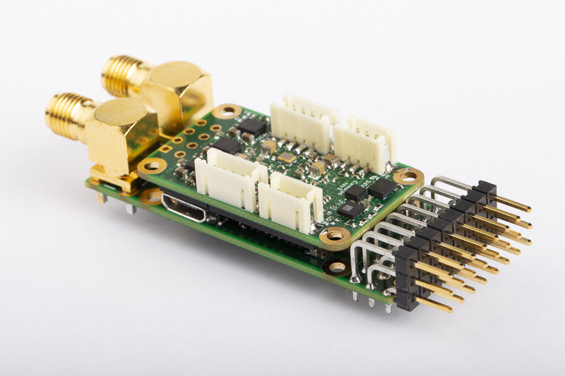
It has been a few years since I first assembled a prototype flight controller built around an FPGA, having been thoroughly distracted by work and thesis writing it’s about time I updated the design. So I hereby present Cormorant!
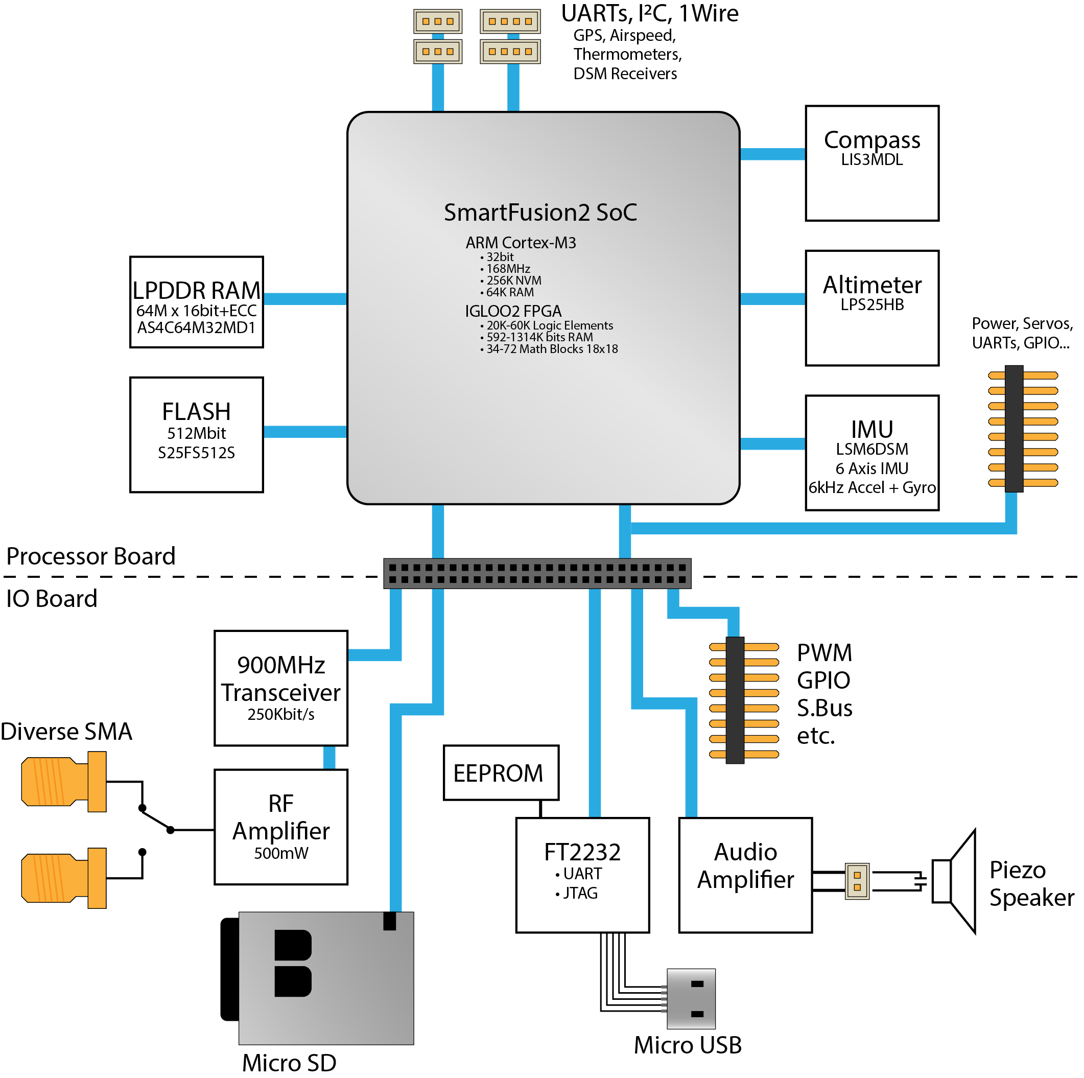
The concept is the same as before: motion sensors, actuator control, communication and of course the FPGA. All of these have come a long way since my original ProASIC3 design, and CPU/FPGA “SoCs” have become common. This new design centres around a SmartFusion2 SoC which uses the FPGA fabric of an igloo2 paired with a Cortex-M3 CPU.
The FPGA uses FLASH memory to store the logic configuration, as opposed to SRAM which most other brands use. This means the configuration is persistent during power down, static power consumption is reduced, and most significantly the logic configuration is not susceptible to ionising radiation effects (SEEs). Using an FPGA also greatly simplifies meeting real-time constraints and determinism, even in high frequency applications such as motor controllers.
Prototypes arrived a few weeks ago and I’ve been frantically porting code from the previous platform. So far they’re performing exactly as designed -which is a relief.
The flight controller is implemented on a single board as a System-on-Module. This contains the processing and memory elements as well as the compass, barometer, accelerometer and gyroscopes. This should include everything required to autonomously control an aircraft in a tiny 20x34x4mm package.
While the SoM is intended to be a complete system, there are many peripherals and conveniences that are typically required in a UAV system. These can be provided by a baseboard that mates with the 40 pin header on the SoM depending on the requirements of the application.
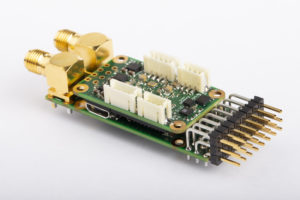
The first baseboard I’ve implemented provides a 900MHz data radio, programming & USB serial interface, SD card, audio output and standard 8 channel servo header. The baseboard measures 20x67x14mm and with the SoM attached the entire unit weighs 18.5g.
Unlike the previous design I’ve decided not to include a GPS or airspeed indicator on the central flight controller. This is due to the fact that these require routing pneumatic tubes or RF cables through the aircraft to locations that are more suitable for these devices; it’s much easier to route a couple of data wires instead.
As my main area of focus is on solar power gliders, I’ve tried to minimise the power consumption. The design is expected to require less than 100mW at 5V which is true for a minimally functional system. However the power consumption can increase drastically depending on which peripherals and features are used such as the CPU and external RAM (neither of which are required for a flight controller).
There are actually quite a number of topics to cover in this design, as well as a whole heap of technical details and specification. I’ll definitely be posting more on these as I find the motivation.
