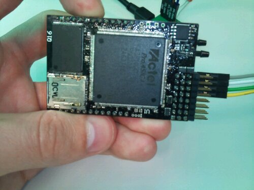
The Asity prototype has been assembled and actually appears to work! 😀
For those of you unaware, Asity is the avionics board I’ve spent the last 6 months designing and intend to use to control my unmanned aircraft.
I spent roughly two days with my solder paste and frying pan assembling it. The order was important as some solder joints are impossible to correct once they are surrounded by components, so I had to reflow the top layer a few times to get everything on. The bottom was completely hand soldered and I’m seriously considering the $400 for a new soldering station with a much smaller tip. After everything was on I then had to spend a very tedious few hours tracking down and correcting shorts. Eventually the meter said it was all good and I powered it up. Thankfully no smoke escaped.
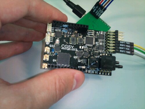
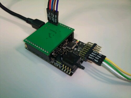 Asity with the USB interface and two JTAG ports attachedThe next trick was to try actually talking to it. I had trouble using Altium’s JTAG adapter at first. There seems to be some signal integrity issue over that header. The solution at the moment is a 10nF capacitor from the TCK line to ground.
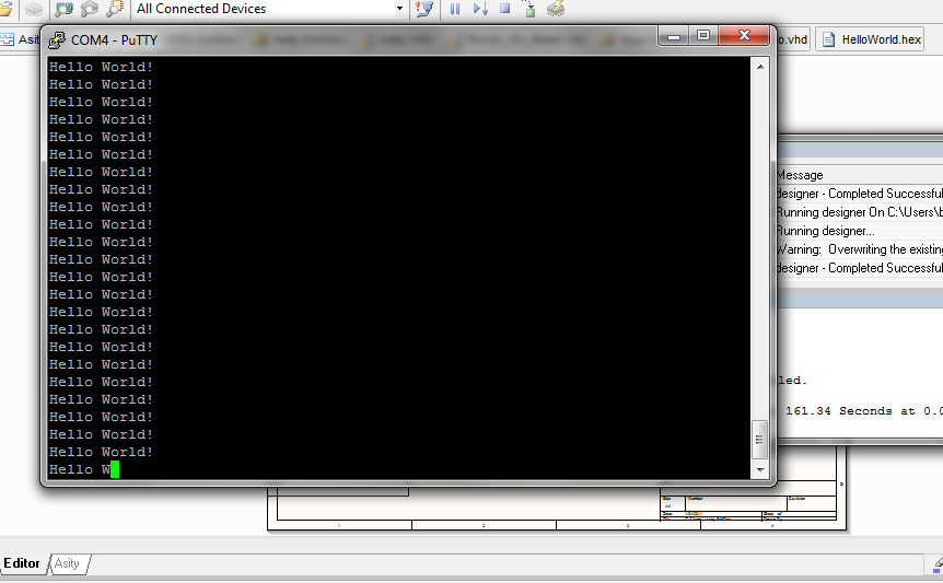
To my amazement I was able to connect to the FPGA and even load some firmware onto it. I started with a simple demo I had made earlier on my Spartan 3E dev board, which repeatedly reads some bytes from a block RAM and sends them to the USB interface. I soon realised that the bit file uploaded to an Actel FPGA doesn’t actually include RAM initialization data, so I found Asity spewing random gibberish at me. After realising this and manually initializing the RAM, I had my demo working.
Tadaa!
My task is now to write the firmware to access all the peripheral devices I included and find out which of those work and which ones don’t. I hope to get at least the GPS working and able to record data to the SD card within a week so I can start logging data from actual flights.
