Controlling Zynq PL Clocks in Linux Userspace

The Xilinx Zynq Ultrascale devices seem to have this covered, but I struggled to find much info on how to do this with the Zynq 7000 parts.  Here’s my notes on both platforms.

With a 4.19 kernel, the Xilinx PL clock enabler (XILINX_FCLK) is the driver you need.  This will expose any compatible = “xlnx,fclk” device-tree nodes to userspace through sysfs.  On Zynq this is something like

# echo 150000000 > /sys/devices/soc0/fclk0/set_rate
# cat /sys/devices/soc0/fclk0/set_rate
142857142  # obviously some PLL rounding to deal with

on ZynqMP

# echo 150000000 > /sys/devices/platform/fclk0/set_rate
# cat /sys/devices/platform/fclk0/set_rate
133333332  # obviously some PLL rounding to deal with

The ZynqMP dtsi’s already have fclk nodes supplied from zynqmp-clk-ccf.dtsi.  My Zynq dts didn’t (probably because it was branched many years ago…) but they can be added like:

fclk0: fclk0 {
    status = "okay";
    compatible = "xlnx,fclk";
    clocks = <&clkc 15>;
};

The PL clocks on the Zynq are <&clkc 15>, <&clkc 16>, <&clkc 17> and <&clkc 18>.  On the ZynqMP they are <&zynqmp_clk PL0_REF> etc. (if you #include <dt-bindings/clock/xlnx-zynqmp-clk.h>).

If you don’t want to set clock frequencies from userspace, you can use ‘assigned-clocks’ in any device tree node that seems relevant.

&custom-thing {
    assigned-clocks = <&clkc 15>, <&clkc 16>;
    assigned-clock-rates = <250000000>,
                           <100000000>;
};

Hope this saves someone else some time.

Cormorant Power Consumption

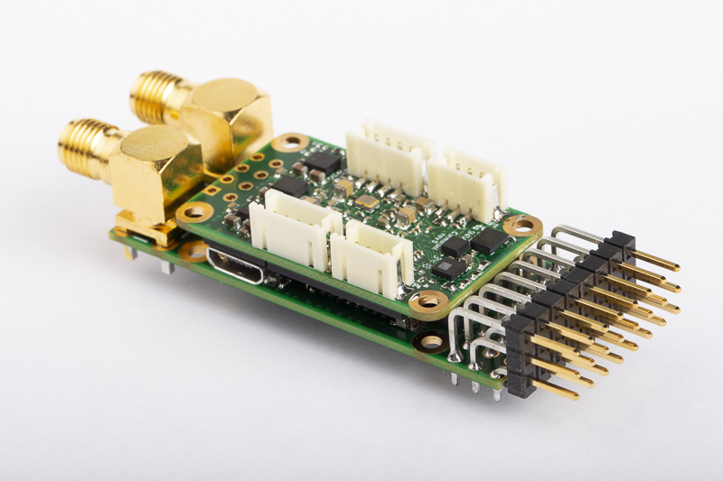
I’ve been a bit slow testing my Cormorant prototypes over the last few months.  I have managed to complete the drivers for the IMU sensors and the data radio which cover most of the important hardware devices, so I thought now would be a good time to measure the power consumption.  This is not just one simple number however, as Cormorant has many peripheral devices with many configurations each consuming different amounts of power.

Continue reading “Cormorant Power Consumption”

Cormorant. A New FPGA Based Autopilot

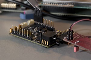
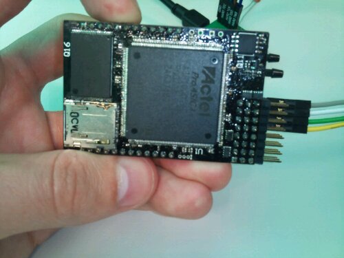
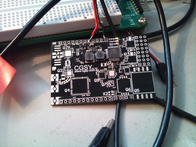
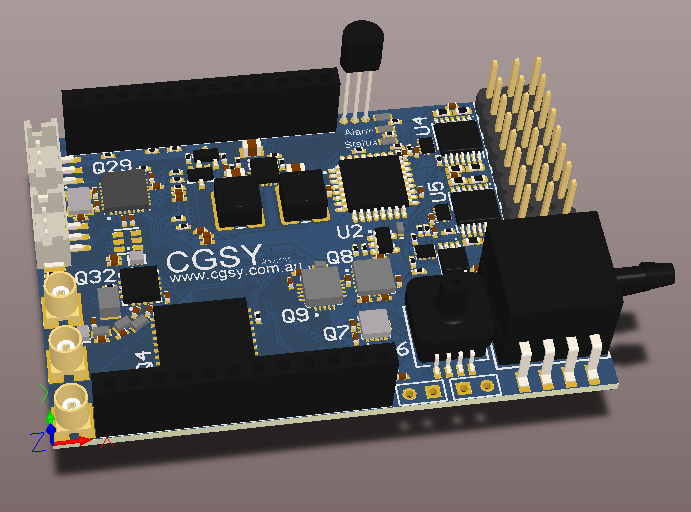
It has been a few years since I first assembled a prototype flight controller built around an FPGA, having been thoroughly distracted by work and thesis writing it’s about time I updated the design.  So I hereby present Cormorant!

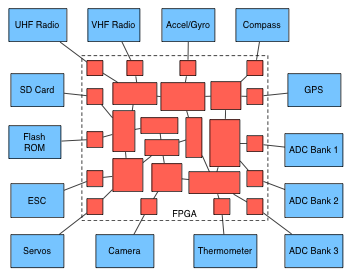
The concept is the same as before: motion sensors, actuator control, communication and of course the FPGA.  All of these have come a long way since my original ProASIC3 design, and CPU/FPGA “SoCs” have become common.  This new design centres around a SmartFusion2 SoC which uses the FPGA fabric of an igloo2 paired with a Cortex-M3 CPU.

Continue reading “Cormorant. A New FPGA Based Autopilot”

Custom ISR Prologue in AVR C

I fell into a situation recently where I was relying on pin change (PCINT) interrupts to decode a serial protocol. This meant I needed to be able to detect if the interrupt was triggered by a rising or falling edge. This particular protocol can have pulses as short as 1uS (8 CPU cycles) so in order to tell if the pin was rising or falling I need to sample it within 8 cycles of it actually happening. Adding time for the pin synchroniser and a non-detirministic ISR entry up to 7 cycles-ish, by the time the ISR starts you’re usually already too late… won’t stop me trying though!
Continue reading “Custom ISR Prologue in AVR C”

Ubuntu on IGEPv2

Preface

This is a short guide to getting Ubuntu running on the IGEPv2 Rev C from a bootable SD card.  There are a few guides around that I’ve based various sections on, but I couldn’t find a complete howto that was up to date with the current hardware.  Most credit goes to Michael Opdenacker of Free Electrons.

Continue reading “Ubuntu on IGEPv2”

Sensor Film Review

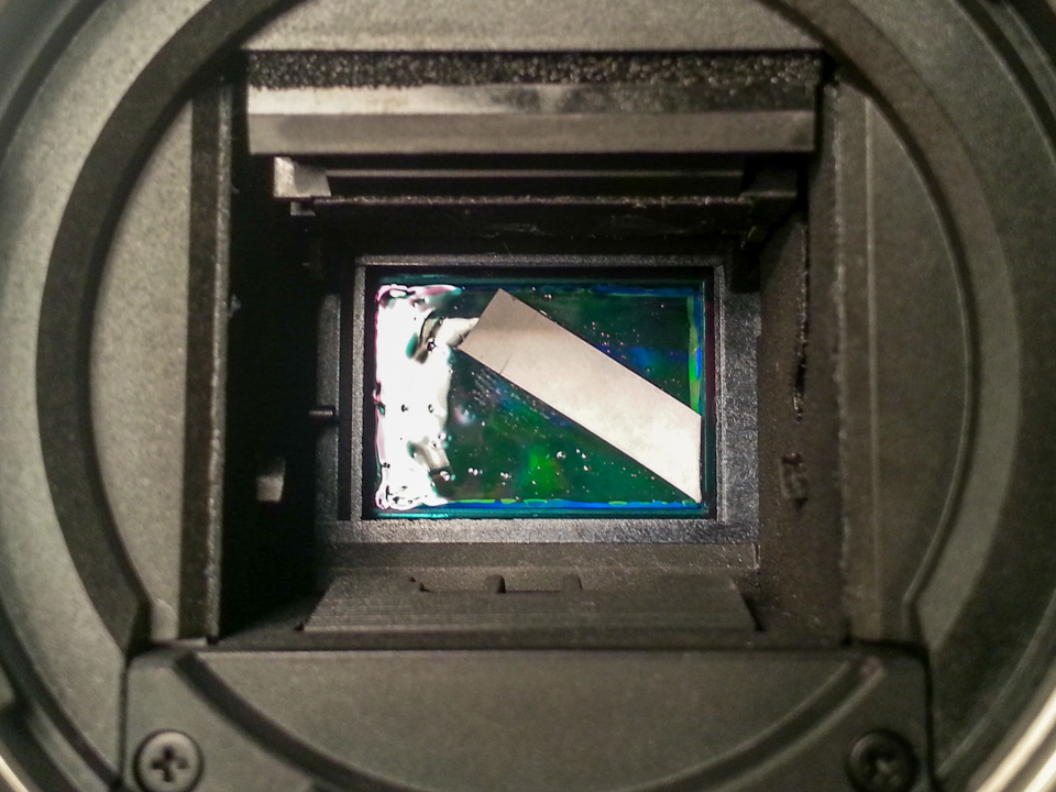
I’ve recently started noticing some dust specks in the photos from my DSLR which are starting to bug me.  In fact I’ve never actually seen my camera’s sensor completely clean as they often come preloaded with dust from the factory.

Before

I’ve made some attempts at cleaning the sensor (it’s actually the low-pass filter infront of the sensor, but I’m just gonna call the whole thing ‘the sensor’) but haven’t had much luck.  Anyone who has tried poking around in a $1000+ camera with various cleaning implements will know how stressful this process can be. Continue reading “Sensor Film Review”

Processing Architectures

So I was listening to a recent episode of The Amp Hour; “An off-the-cuff radio show and podcast for electronics enthusiasts and professionals“, and Chris & Dave got onto the topic of custom logic implemented in an FPGA vs a hard or soft core processor (around 57 minutes into episode 98).  This is a discussion very close to my current work and I’m probably in a very small minority so I figure I should speak up. Continue reading “Processing Architectures”

Outback Challenge Deliverable 2 Submitted

So there have been some sleepless nights recently as the deadline for the Outback Challenge second deliverable passed this afternoon.  I managed to get my report in by the skin of my teeth after some email troubles (still waiting on the confirmation from the organisers :S ).

Each team had to submit a technical report that details the design of their aircraft and their risk management strategies.  We also had to compile a video that demonstrates our on field setup procedure, takeoff and landing and how the aircraft handles carrying and dropping the payload. Continue reading “Outback Challenge Deliverable 2 Submitted”

Pulsar 4E Bottle Drop Tests

With the second deliverable for the Outback Challenge quickly approaching it was about time I discovered if the Pulsar could even carry the all important bottle of water.

After a successful maiden flight I took the Pulsar home and began hacking away at it with a rotary tool.  The idea was to cut the holes I had planned in the fuselage so the bottle could be attached and the camera could see.  This is pretty much what I achieved, albeit with a few more slips and scratches then I had hoped for. Continue reading “Pulsar 4E Bottle Drop Tests”

The Pulsar’s Maiden Flight

So it’s been 18 days short of a year since the Pulsar arrived in a giant box.  Since then there has been a lot of time spent measuring and modelling and generally designing to figure out how to fill it with stuff to ready it for the outback challenge.

It took a few attempts at various components to get the fit right.  Measuring its sleek, sexy curves proved to be quite difficult.  The last few days have been spent shifting things around to perfect the balance and program my recently replaced radio equipment. Continue reading “The Pulsar’s Maiden Flight”

DSM2/DSMX Remote Receiver Protocol

I’ve been playing around with my transmitter a lot recently as flying season is starting up again and the darn thing isn’t working well.  Likewise, the receiver I’ve just installed in the Pulsar refuses to bind to my radio.  So a big fail all round by Spektrum, which has lead me to seek alternative solutions.

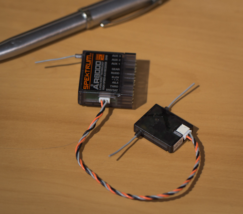
The AR8000 Receiver with a remote receiver attached

I’ve seen a few forum threads discussing the serial protocol used by Spektrum’s remote receivers and it seems pretty straight forward to collect the data from them; bypassing the main receiver completely.  Unfortunately the only decent write up of the details that I could find was a bit out of date, and only covered the 7 channel case.  So here is what I’ve learnt from poking this device with an oscilloscope and a logic analyser for a few hours. Continue reading “DSM2/DSMX Remote Receiver Protocol”

Meet the Pulsar 4E

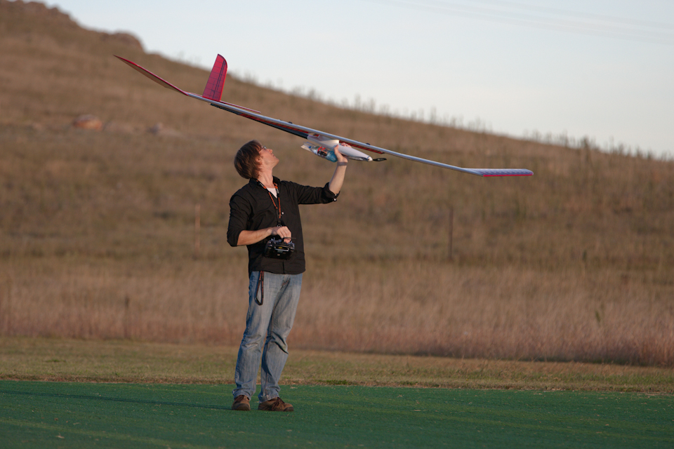
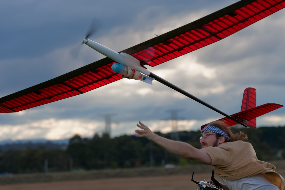
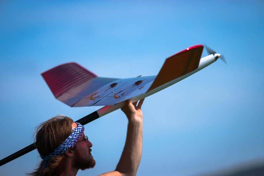
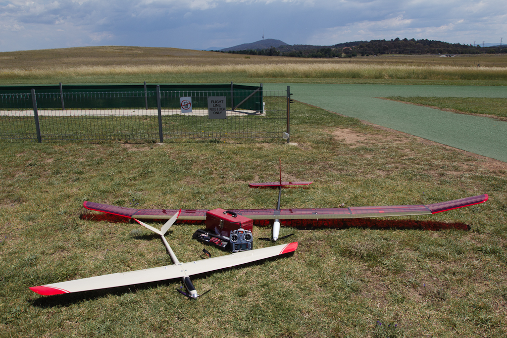
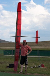
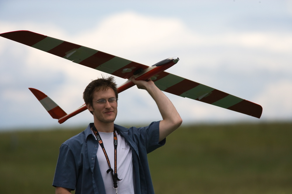
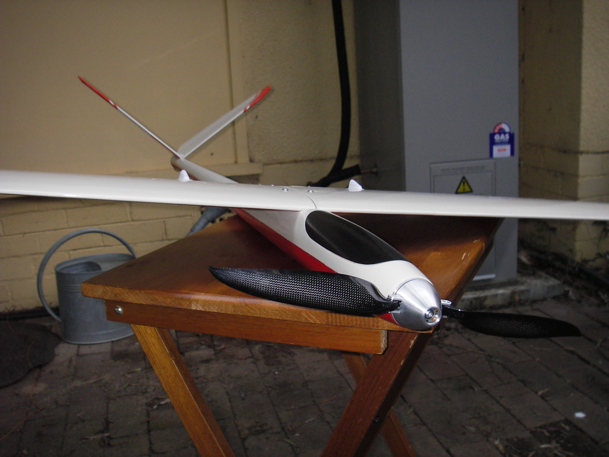
As I’ve mentioned a bunch of times on this blog and to anyone I came into contact with over the last 12 months: I’m building a rather large glider to compete in the Outback Challenge.  I recently finished collecting and assembling parts and am keen to see it get off the ground when all the stars align.  You’ll notice that it’s big… really big. And no;  I’m not short 😛

The Pulsar range of gliders should be familiar to most RC enthusiasts.  They are typically a slow, light weight and very well built aircraft featuring enough carbon fiber to make most cyclist jealous.  It is not a scale model, so it doesn’t look like a traditional manned glider.  Instead it has been designed from scratch to be a very efficient radio controlled aircraft.

The Pulsar 4E is the largest of the Pulsar series with a wingspan of 4 meters.  The one I have assembled weighs 2280 grams without a payload, which is expected to be a little over 500 grams of water and bottle.  I have fitted a modest 550 Watt Neu motor to the front which I expect will be just enough power to maintain cruise speed while climbing vertically.

So far, we’ve taken the Pulsar to the airfield twice in attempts to fly it.  Unfortunately we’ve been foiled by gusty winds and some really buggy firmware for my transmitter.  At least it hasn’t been destroyed yet.

I’ll save my rant about Spektrum’s latest DX8 firmware (2.04) being a terrible example of embedded software and something I consider quite dangerous, as it is sometimes in control of very large and fast aircraft.  I’ve downgraded to version 2.01 which I will use cautiously for the time being.

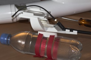
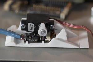
I still have to add the avionics I’ve been working on.  I had some plastic mounts printed that served as both the dropping mechanism for the payload as well as holding the electronics in place.  Unfortunately some of the dimensions were a bit off and it failed at both of those things.  I have some more coming in a couple of weeks and will hopefully have written enough code to make that worthwhile by then.

So while I wasn’t flying anything today, I took the time to make this view of airfield (3MB).  Enjoy!

New Avionics

I recently completed building the first of my new version of Asity, the avionics I plan to use in all my UAV activities.  The main improvements in this version are the new inertial sensor chip I’m using.  I previously had a separate accelerometer and gyroscope.  Now I’m using the MPU-6000, which does both much better than what I had.  It also does some motion processing of its own which I am dubious about, but I’m going to try it out and see if it can save me writing my own.

The top side of Asity

There are also a number a bug fixes I noticed while playing around with the last version.  These are silly things like not including a bias inductor on a powered GPS antenna, supplying the wrong voltage to my compass, and forgetting to put decent pull-up resistors on an I2C bus or two.  Fingers crossed that there aren’t more I didn’t find.

The most significant improvements are from a manufacturing view.  Given that I’m assembling this by hand with a frying pan, I need to put some effort into the design to make it as easy as possible.  This involved swapping a bunch of 0402 sized capacitors & resistors for their slightly larger 0603 versions.  I also had to consider how I can fix things as I assemble it, so trying not to block access to my soldering iron.  I also have a planned out assembly procedure that involves testing at a few stages.  It’s much easier to fix some things before the board is complete, so I try to make sure it all works before continuing.  Applying solder paste tends to be the messiest part and results in lots of tiny conductive balls rolling around your components if you do make a mess of it.  I ordered some Kapton stencil from OHARARP to make this easier.

The bottom side of Asity

The bottom side of Asity is all hand soldered, so I made sure to choose the components and their layout wisely.  This means: no 0402 sized components; no packages with hidden leads (QFN, BGA), and; everything nicely spaced so I can get my soldering iron between things.  This last point may have been neglected a little, mostly because there isn’t enough space on the board.

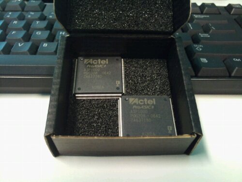
I took two attempts to solder the FPGA on the bottom.  The first time was a bit of a nightmare and I spent way too long poking at it with the iron to clear shorts etc.  I decided that I had probably butchered the chip and that I didn’t really want it flying my aircraft.  So I removed the first one completely, cleaned the pads and started again with a fresh one.  It wasn’t a cheap part, but given the components on the others side aren’t particularly cheep either, and they were already working, I decided it was for the best.  The second FPGA went on with much less fuss and also seems to work fine now.

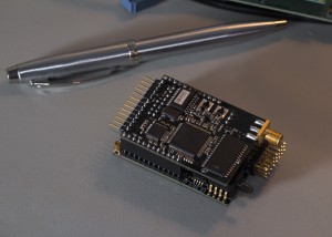
The daughter board

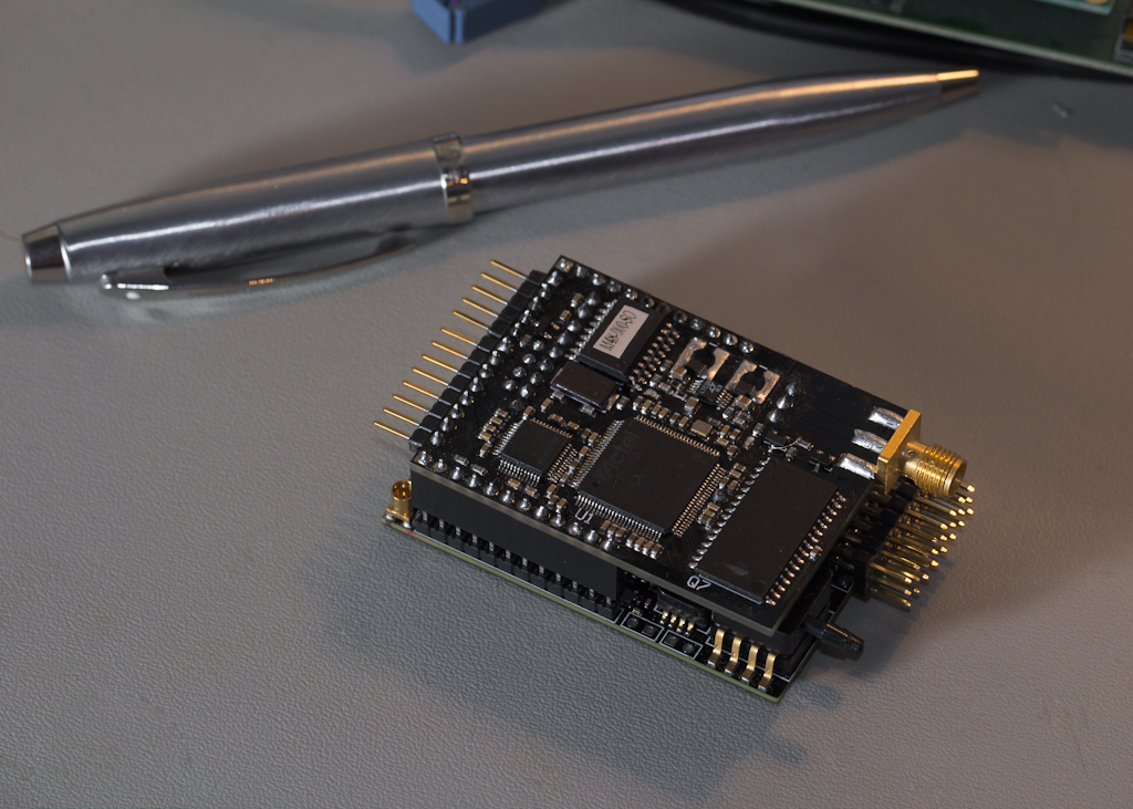
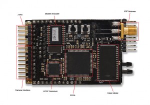
I’ve also assembled the daughter board that fits on top of Asity onboard the aircraft.  This board includes a VHF radio to act as a backup link if the main UHF fails.  It also has an interface to the camera in the nose of the aircraft as well as another FPGA and some RAM to process images data.

So far everything has tested well.  I haven’t tried the radios yet, as I still need to assemble the other end of the link, but I’m feeling pretty confident about everything else.  It all fits together nicely (there’s a massive radio module sandwiched between the two halves) and only weighs 53g assembled.  Now I just have to fill it with useful code.

My Outback Challenge Aircraft

So the massive lack of updates recently has been due to me gaining knowledge in the business management and marketing fields.  I’ve been doing some more coursework to complement my PhD and make me generally more entrepreneurial.  A fairly painful experience so far, and one which will last for another six months.

Between paragraphs of my business plan I did manage to update the designs for Asity as well as complete the CAD models for the parts I need for the Pulsar.  This combination is geared towards completing the Outback Challenge while still being useful to my research.  So here’s an attempt to illustrate what I’m building.

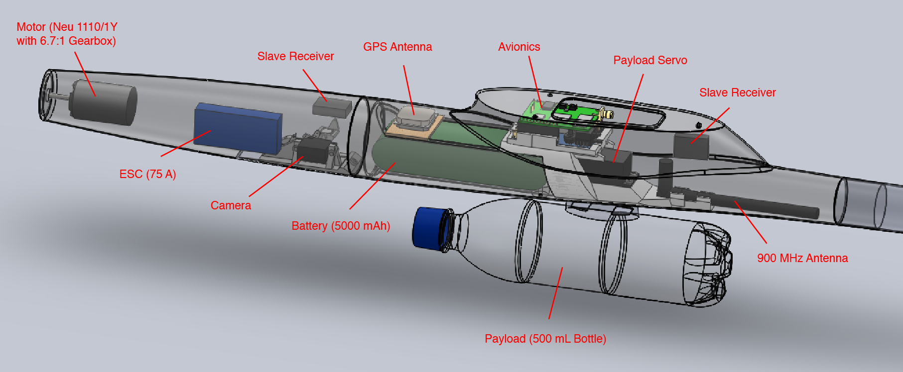
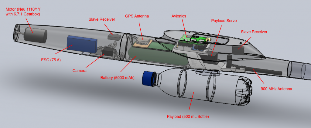
This is the layout of the components I intend to include in the Pulsar4E airframe I’ve got lying around.  It include the typical motor-ESC-battery you’d find in a modern electric RC plane as well as the avionics and camera components I’ve been working on.  You’ll also notice the whopping great water bottle hanging from the bottom.  This is of course the all important payload that needs to be delivered to Joe.

The motor, Electronic Speed Controller (ESC) and propeller blades are being carefully selected to allow the whole aircraft to climb vertically with a payload when the throttle is flat out.  Once it reaches a comfy altitude, the motor is switched off and the propellor folds back.  I’m using a Neu 1110/1Y with 6.7:1 gearbox with a 75A ICE Lite ESC from Castle Creations.  I’ve picked a few props with varying pitches to experiment with.  I’m expecting the aircraft’s takeoff weight to be around 3 kg, and so aiming for a static thrust slightly higher than that.

The moulded parts shown are all coming from Shapeways.  Results so far are promising.  The quality is great and my measurements of the curvy fuselage are actually quite accurate.  Not so accurate are the dimensions I chose for the servo components in the payload dropping mechanism, so I will need a few bit reprinted.

The payload is suspended from a pylon by two polypropylene webbing straps.  I will also add some velcro between the pylon and bottle to prevent it from sliding back and forth.  The pylon fits a hole in the bottom of the fuselage and mates with a beefy servo with a metal horn.


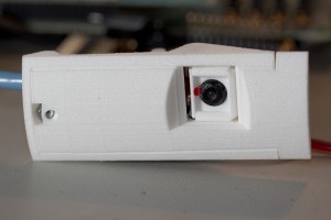
The camera is towards the front of the aircraft and also needs a hole cut in the fuselage.  The camera I’ll be using is a fairly cheep 1.3MP CMOS sensor; the kind you would’ve found in a phone from 2005.  It should be just enough to spot a vehicle from 1500ft, and hopefully Joe from 400ft.  I believe the aircraft will be able to stabilise the camera adequately, so I have only included one servo to compensate for the pitch of aircraft.  As I’ll be gliding most of this time, I’ll usually be pitched down and will need to adjust the camera.

I designed a small board to transfer data from the camera back to the main processors in the center of the aircraft.  The board pictured includes a small LVDS transceiver that will translate the parallel interface of the camera into a high speed serial stream, back up the Cat5 cable to a similar chip which will recreate the parallel interface and feed it into an FPGA.  From there it will be appropriately processed and fed into the UHF radio to be sent to the ground.

I’ve also built the first of my latest version of Asity; the avionics I’m developing.  I’ll go in to more detail about this in another post, so for now here is a pretty picture:


Research Poster… Again

So it’s that time of year again where all of us graduate students here at the College of Engineering and Computer Science are made to produce posters for our projects.

My effort from last year is still available over here if you were interested in comparing the two.

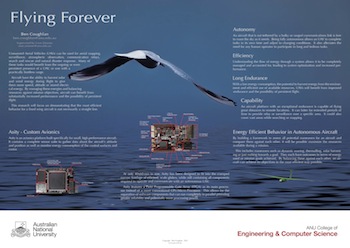
The concept remains the same, but this year has a few more updates on the direction of my research and some pretty pictures of Asity.  The albatross is still around.

Research Poster (PDF 2MB)

So with that out of the way, I’ll get back to doing some real work 😛

Pan/Tilt Prototype is Complete

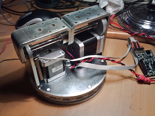
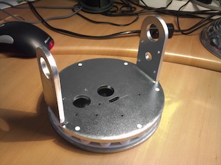
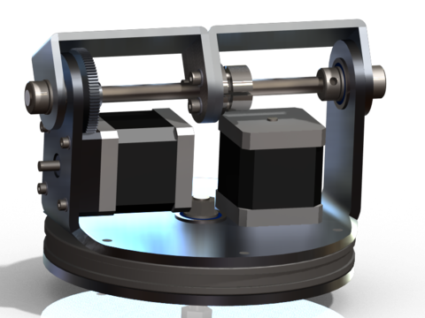
The pan/tilt hardware for my antenna tracking tripod is finished.  It even looks kinda like my design :D.

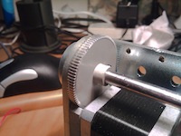
With the layer of zinc I didn’t account for, everything is actually pretty tight (after some sanding).  There is no play anywhere except for some slight backlash in the gears.  The mounting brackets don’t slide on the shaft and the chassis doesn’t rock on the main bearing at all.

The unit as a whole is pretty solid and weighs more than my scales will tell me.  My CAD software tells me it’s around 4 to 5 kg.

Unfortunately the small gears I received had the wrong bore size.  I couldn’t be bothered having new ones shipped from the US so I decided to drill them a bit larger myself.  This ended in fairly average results.  The gears fit the motor shaft fine, but they have a bit of a ‘wobble’ as they rotate which is less than ideal.  They’ll work for testing, but will be an issue when I put some load on them.  Some new gears from a local supplier are on the way.

The bends in the metal were off by a degree or two.  Not much, but the very tight tolerance on the shaft mounts mean that if the holes don’t line up then the shaft jams when I try to assemble it.  This was solved with my trusty sledge hammer, which was odd given the 0.05mm tolerance.

The electronics and their mounting are probably one aspect I put the least thought into.  I’m just using the Pololu A4988 controllers and mounting them in a very flimsy plastic frame.  It’s not my proudest moment, but will work for now.

I’d actually like to make my own board at some point.  The Pololu controllers are a bit pricey compared to the chip that actually does the work.  They also won’t easily accommodate a heatsink.  Without the heatsink I can only run the motors at about half their maximum power.  My own board would have actual mounting holes and a heatsink making the whole arrangement much neater.

The gears come with an M2 grub screw which is pretty small considering the load I’ll be putting on them.  These tiny screws need a 0.9mm hex key which is very small and not amongst my collection.  It also doesn’t appear in any sets I could find in the shops.

I had a go at tapping a new M3 hole for a bigger, more convenient grub screw.  This pretty much failed as the hole for a set screw is very shallow, and a hand-tapped thread tends to be crappy at the top.  So there wasn’t enough thread for the bigger grub screws.  I’ve decided to order the tiny hex key and see how the small screws go.

Right now I’ve mounted two SLA batteries on the chassis itself along with Asity as the controller.  This should let me play with it, without worrying about tangling cables.  I still haven’t written any software to control it, so no movement yet.

More Pan/Tilt Parts

The main chassis for the my pan/tilt mount is made from 5mm steel plate.  This is a rather difficult material to work with in my garage, so I opted for the services of some professionals with industrial size lasers and presses.

The lasers, as you would expect, are very precise.  All the cuts are spot on.  My main concern was with the bends.  Even with a robotic press, bending thick metals can be a bit unpredictable.  Even so, the bends came within 0.5 mm of where they needed to be.

I took the parts straight to the electroplater across the road and had him put a zinc coating on all the parts.  The process cleaned off all the crumbs from the laser as well as the heat-scale and the zinc made them nice and shiny.  Over all I’m very happy with the finish.

The parts are completely rigid, at least when tested with my puny human muscles.  The structure should be capable of quite a significant load.  The weakest point in the design will be the strength of the motors.  This isn’t an issue if the load is balanced around the rotation axes.

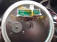
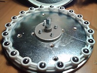
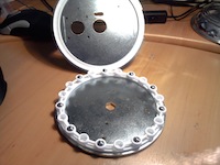
The plastic bearing runs mate with the steel plate of the base and the chassis with six extrusions.  The fit was actually quite tight, but after some squeezing they fit and stay together perfectly.

The steel balls fit the spacer perfectly as well.  It takes a bit of force to insert them, but once they’re in, they stay in while still rolling freely.  With all the balls inserted (I only have 9 at the moment), the spacer is sandwiched between the two runs.  The two halves spin freely on the main bearing and the spacer doesn’t rest on the bottom run.

There is one last package to arrive containing bearings, nuts & bolts.  Hopefully it will be here by the end of the week.

Pan/Tilt Prototype Underway

I managed to convince myself that pursuing my pan/tilt design was a good idea.  The design itself is complete and I have sourced all the parts I need.  Some parts have already started arriving.

If you don’t know what I’m talking about, or would like to fit the parts described below to the design then you can find the details here.

The parts from Shapeways arrived today.  Shapeways is a 3D printing service, an activity I had hoped to achieve with my ill-fated RepRap.  I’ll fix it one day… Anywho! Shapeways prints much finer things than a RepRap is capable of and offers a few more choices of material.

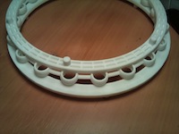
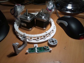
The big white circle is the bearing that the whole pan/tilt mount sits on.  It takes the weight while still allowing it to rotate.  Given it’s relatively large diameter, it should keep everything stable.

The top and bottom part mate with the steel base plate and the main chassis while providing a groove for some steel balls to roll in.  The middle is a spacer to keep the balls evenly spaced.

The whole mechanism is held by a central bolt which clamps the two halves together against this bearing.

This is Shapeways laser sintered plastic.  It can be pretty strong if you don’t make it too thin.  I’m very happy with the accuracy of the print.  Remind me to go back and tighten the tolerances in my design.

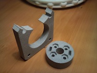
The squareish part on the left here is a motor brace.  It fits between one of the motors and the chassis to allow space for gears to turn.

I made the decision to place the ’tilt’ gears inside the chassis rather than on the outside face.  This is for a few minor reasons including aesthetic, symmetry and safety.  This way both outside faces are flush and there are no exposed gear teeth to byte hapless fingers.

The round part is a locking hub, supposed to bolt to the face of a panel and lock it to a shaft with two set-screws.

This kind of part is surprisingly difficult to find for a reasonable price and in the right size.  I managed to find some imperial sized bits that are ‘close enough’ from ServoCity.  This printed version is just in case I can’t use the steel ones.

Both of these are printed in alumide; a combination of the plastic above and aluminium powder.  Not quite as strong as the plastic but much harder.  The motor brace will work fine but I am skeptical about the locking hub.  Fingers crossed those ServoCity hubs are suitable.

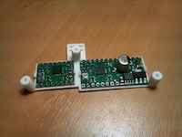
The last piece I’ve ordered from Shapeways is a PCB bracket.  This bolts onto the chassis and holds the controller PCBs for the pan/tilt mount.

I may have made this a little bit too skinny.  It was one of those situations where it looked fine in CAD on my computer and I failed to realise just how small it really was.

This one successfully holds the PCBs but it does do so under some tension.  I think it’ll be fine to make the prototype work, but I’ll probably replace it with a sturdier version at some point.

The actual PCBs I’m using are pretty straight forward stepper controllers from Little Bird.  Thanks to Madeline at Little Bird for adding them to their catalogue after my nagging.

These use the A4988 controller which allows 2 amps per motor coil, provides a very simple interface and allows up to 1/16th stepping.

The breakout boards will suffice for now, but if I decide to make lots of pan tilt mounts I will probably make my own boards to go with it.

The remaining parts to order include numerous nuts & bolts as well as the rather important steel parts.  I’m actually getting the steel parts laser cut and bent for me.  It’s not cheap, but it saves me struggling to form steel plate in my backyard.  Hopefully I will have a completed prototype in late June.

Pan/Tilt Heads for Antenna Tracking

I’ve fallen back into hardware mode before making any significant progress recently.  I have to say I enjoy it more, and I do have so much hardware to come up with for the Outback Challenge.
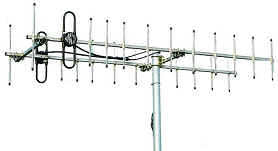
The last week has been focused on antenna tracking.  Basically I have two large yagi antennas that I need to keep pointed at the aircraft which requires a pan/tilt head mounted on a mast.

The antennas are quite large, weighing about 4.3Kg total and being about 2m long. I’d also like the mount to be stable enough to mount a camera with a suitably large lens.  Having something automatically record the aircraft will make documentation much easier.
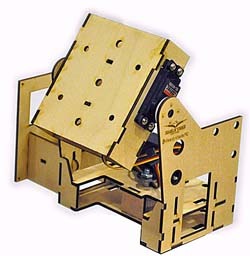
This puts me in an awkward range in terms of pan/tilt heads. The options either seem too light and under-powered, or prohibitively expensive.

Not considering the tiny, point-and-shoot camera variety; the affordable end of the scale looks to have two serious options (although if there are any out there I have missed I would love to know about them).

The most popular in the FPV community seems to be this thing, annoyingly unnamed.  Made from laser cut wood it is more than capable of swinging a single patch antenna around, but will definitely struggle under my yagis.

It’s nice and cheap at $90 including servos.

The pan/tilt head closest to my specs is the AT Pro-1000.  This is made completely of aluminium and when using the supplied HS645MG servo on the tilt axis there is plenty of torque, about 9.5Kg.cm.

The main drawback of this design is that it is definitely aimed at patch antennas, with large, wide structural members.  They do provide a bracket for mounting a single, smaller yagi, however getting both of my antennas on there will be awkward.
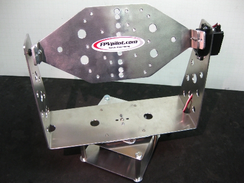
AT Pro-1000The AT Pro-1000 weighs about 1Kg and is roughly 30cm wide.  It’s price point is almost exactly where I am looking at $220 including servos and yagi bracket.

So it seems easy enough to swing patch antennas around.  Unfortunately patch antennas don’t offer the gain or the focus of a large yagi.  Outback Joe didn’t exactly get lost in a convenient place and maintaining comms is pretty critical.

The other end of the scale comes with incredible specs and some pretty fantastic features.  It also comes with a bunch of request for quote forms…
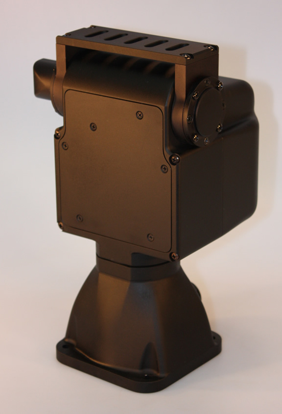
D48ESomething like the D48E or even it’s smaller cousins would easily meet my needs, and then some.

Capable of swinging over 10Kg around at 100 degrees per second (probably not at the same time) and incredible 0.003 degree tilt resolution.

The offerings from FLIR also boast ethernet integrated and all weather operation.

These are actually available from distributers in the US and Canada, but even the smallest was well over $2000.  Far beyond my budget, and requirements for that matter.

The one major difference is the design.  The D48E has more uses in mind than just patch antennas and so only offers a single mounting bracket for any accessories, making it easier to mount custom hardware.

So like most of my product searches recently, I’ve resolved to design and build one myself.  I’d be lying if I said I was disappointed 😛

Over the last week I’ve been madly scheming and searching the interwebs for suppliers and I think I’ve gotten to a draft I can actually build in my garage.

I originally wanted to use 6mm steel plate to ensure it was strong and rigid.  I eventually realised that my tools are not up to steel, especially if I were to try hot-forming the bends.  I considered having someone machine the steel for me but decided that I didn’t really need steel at all.

To simplify things a few orders of magnitude, I decided on 6060/1 aluminium in stock extruded channel.  Aluminium is much easier to work with the in the backyard, and using stock in the right shape meant that my job was already half done.

At the moment I’m trying to decide between servos or stepper motors, and where to find the cheapest parts ($50 for that hub in the middle! seriously!) but the shape is pretty much fixed.  The antennas will mount towards the ends of a bar bolted to the top face.

The base diameter is 150mm and sits completely on a custom bearing, so there should be very little wobble.  I’m aiming to keep the entire cost below $300.
Asity Scores a GPS Position Lock

Today I was relieved to get some GPS data out of my Asity prototype(s).  Since assembling one the other week there have been a few set backs, but as of this news I’m still on track.

The first one I made did seem to work at the time, however the FPGA has since stopped working.  It seems it has lost the ability to write program data to its internal FLASH and nothing I do seems to make a difference.  It appears the fault is completely internal to the chip and I’m putting it down to my shoddy assembly, it was on a frying pan after all.

To keep things moving I decided to build the second prototype.  I had always intended to build two; the second being a stripped down version including only the sensors needed to operate the antenna tracking on the ground, as well as the radio.

This second board was much neater having learnt some lessons from assembling the first.  The FPGA works and accepts my code without issue.  However I found the GPS was not functioning.  After checking all the solder joints I still have no idea why…

Eventually I resorted to mangling the two half working boards in to one fully functional board.

This was simply a process of balancing leads on the data pins of the working GPS and hooking them up to some of the servo signals on the other board (I love FPGAs 🙂 ).  This worked as expected and I was able to talk to the GPS.  However I was unable to get a position lock from it.

After pondering a while I gave a mate a call who I usually turn to in times of such technical conundrums.  He was surprisingly quick to point out that I was using an active antenna but not actually supplying any power to it.  It turns out I had completely missed the required inductor between VCC and the GPS’s RF line.

The datasheet for the GPS in question suggests a 33nH inductor is used to bias an active antenna.  These are quite a lot smaller than the usual components found in labratory stock, and certainly not something found at the local electronics store.  Being impatient, and unwilling to order a bunch of stuff to fill a shipment for a single inductor I decided to improvise.

After ‘jumpers’, inductors are the easiest component to manufacture yourself.  They are just a coil of wire after all.  Unfortunately it has been several years since my high school science teacher tried to teach me the maths involved in coiling an inductor.  Luckily Google was more than willing to provide an ubundance of inductor calculators.

With some trial and error I picked some numbers that looked reasonable and wound some solder wire around a meter probe.  After some more trial and error, I had a coil that was apparently in the right ball park.

With my home made inductor in place, I was amazed to find that I could actually track some satellites.  I’ve managed to find 12 satellites while sitting Asity inside, on my desk.  Amusingly they’re all to the northwest which is where my window happens to face.

So the GPS works fantastically (on half of my boards).  The faults I have uncovered are not consistent for both boards, other than the missing inductor of course, so I’m still confident I can make this design work.

Asity Lives! ..and it says ‘hi’.

The Asity prototype has been assembled and actually appears to work! 😀
For those of you unaware, Asity is the avionics board I’ve spent the last 6 months designing and intend to use to control my unmanned aircraft.
I spent roughly two days with my solder paste and frying pan assembling it.  The order was important as some solder joints are impossible to correct once they are surrounded by components, so I had to reflow the top layer a few times to get everything on.  The bottom was completely hand soldered and I’m seriously considering the $400 for a new soldering station with a much smaller tip.  After everything was on I then had to spend a very tedious few hours tracking down and correcting shorts.  Eventually the meter said it was all good and I powered it up.  Thankfully no smoke escaped.

image Asity with the USB interface and two JTAG ports attachedThe next trick was to try actually talking to it.  I had trouble using Altium’s JTAG adapter at first.  There seems to be some signal integrity issue over that header.  The solution at the moment is a 10nF capacitor from the TCK line to ground.
To my amazement I was able to connect to the FPGA and even load some firmware onto it.  I started with a simple demo I had made earlier on my Spartan 3E dev board, which repeatedly reads some bytes from a block RAM and sends them to the USB interface.  I soon realised that the bit file uploaded to an Actel FPGA doesn’t actually include RAM initialization data, so I found Asity spewing random gibberish at me.  After realising this and manually initializing the RAM, I had my demo working.

Tadaa!

My task is now to write the firmware to access all the peripheral devices I included and find out which of those work and which ones don’t.  I hope to get at least the GPS working and able to record data to the SD card within a week so I can start logging data from actual flights.

Pulsar has Arrived

The couriers have visited frequently in the past few weeks, two of them arriving today.  The first brought me the new ADCs I need for the Asity prototype, which I should hopefully have complete sometime tomorrow.
The second courier brought a rather large box containing the Pulsar 4E that I plan to use for the Outback Challenge next year.
This is a big aircraft! compared with the Paprika I built last year, this has twice the wingspan.  It’s 4 meters wide and so far weighs about 1100 grams.  I expect it to weigh a little under 3 Kg once I’ve installed all the other components and the payload.
imageI’m still working on sponsorship for the remaining parts so it probably won’t be airborne for a month.  Right now I’m going nuts with my callipers to try and build a model of the fuselage so I can plan out the other parts I need.  This is one disadvantage of a sleek glider; there isn’t much cabin space to play with.

The Outback Challenge was recently announced as a bi-annual event with the next ‘Search & Rescue’ being held in September 2012.  While this does interfere with my plans significantly, I do appreciate the extra 12 months for development.

Prototype Assembly

So I’ve been waiting for PCBs since christmas before I could continue building the Asity prototype.  My first batch was ordered from BatchPCB and arrived a few weeks ago.  Unfortunatly I couldn’t use these for a number of reasons.
Firstly, the quality of the boards left a bit to be desired.  The solder mask was misaligned slightly and was often missing between the fine pitch pins of the FPGA.  The hot air level finish was also a bit on the bumpy side, and missing from some pads.  These would be ok for larger designs, but fine pitch work is hard enough already so I didn’t risk it.  I’ve used BatchPCB for two layer boards a few times and had no issues, but I don’t think I’ll use their four layer service again.
Second; the gerbers I sent to be manufactured had a bug in them which shorted one of my power rails to ground.  I tracked this down to a bug in Altium, which was quite disturbing.  It has been fixed in version 10.
The last issue was my own fault.  The footprint for my main power regulator was flipped causing me to kick myself repeatedly.
So I fixed my designs and added a few changes I had decided on during the wait and sent off another order; this time to EastPCB in China.  Their website reeks of template and does seem a little ameturish but their quote was significantly below any other manufacturer, so I decided to give them ago.  After two weeks, the boards arrived yesterday and I’m thrilled with how well they turned out.  I chose an immersion tin finish which is much neater than the hot air level on the last boards.  The solder mask is perfect on both sides and a much sexier black instead of the standard green.  As a bonus, they didn’t remove any of the letters on my overlay unlike some others…  It’s nice to have the rev number printed on the boards.  On top of all this the order came back with a full test report and cross section sample taken from my production run.
I spent this afternoon assembling one board.  I haven’t made it easy on myself with the spacing between components, but I’m confident it can all be done on a frying pan.  It will just require a few bakes to get all the parts on.  The power supply and watchdog went on today and everything is working perfectly which I’m thrilled about.  At least now I know that if there are other issues on the board, they will be isolated to a particular component and I can still use the rest.

Turns out I ordered ADCs with the wrong footprint so I’ll have to take a break while I wait for new ones to arrive.  Hopefully I’ll have it completed by the end of next week.

Seeking Sponsorship for the Outback Challenge

So I have decided that it would beneficial to my research and the development of Asity if I attempt to enter this years Outback Rescue Challenge.
I have completed the preliminary designs, costings and schedule and with a lot of help I might actually have a capable aircraft by September.
Given my hands are pretty full completing the software to run on Asity, I am enlisting the help of an undergraduate Software Engineering team to help build (or extend) the software for a Ground Control Station.  I presented my project to them this morning and with any luck I should be meeting a capable team in the next week or so.
I am now appealing to the masses for help funding this endevour.  If you know of anyone who runs a business providing products or services that are relevant to UAV research, the expected audience of the outback challenge, or are just really really nice; please point them towards me.  My current plan is to allocate space for sponsors on the actual aircraft where they can place their name and logo like so:

The money raised will be used to purchase the aircraft itself, manufacture custom hardware and cover things like travel, accommodation and insurance.
I can be contacted at ben.coughlan@cgsy.com.au

The Shape of Things to Come

I may be using this title a little prematurely… I just finished watching Caprica last night.
The last few months of my life (holidays included…) have been spent designing the hardware components for the avionics board I plan to use for my unmanned aircraft.  A few days before Christmas the PCB designs were sent off to the manufacturer signifying the design was complete and ready to be built.   I’ve since spent my time rereading datasheets and conferring with colleagues, praying that there are no significant flaws in the design.
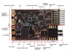
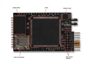
So what is it? Asity is basically a processor, a radio and a collection of sensors that cover everything I need to fly an aircraft autonomously and perform some experiments relevant to my research.  The PCB is 40mm x 60mm with the odd protrusion and will easily with into the fuselage of a glider.  More specifically:

  • Actel ProASIC3 FPGA
  • Atmel ATtiny88
  • 16MB SRAM
  • 32 Mb Flash
  • MicroSD Card Slot
  • GPS
  • 900MHz Transceiver
  • 3 Axis Accelerometer
  • 3 Axis Gyroscope
  • 3 Axis Compass
  • Barometric Pressure Sensor for altitude
  • Differential Pressure Sensor for airspeed
  • Temperature Sensor(s)
  • 8 Servo Channels
  • Current Sensing and power enable on each Servo
  • Flight Pack Voltage Sensing
  • Motor Current Sensing
  • Slave Receiver Headers
  • 12 General IOs

I’m also building an USB daughter board to allow a ground variant to attach to a laptop in the field.Why does the world need another autopilot? There are a number of similar boards available covering a range of applications.  The main difference with Asity is that the processor is a Field Programmable Gate Array (FPGA) rather than a traditional CPU.  I also intend to write the firmware completely in HDL rather than using any ‘soft core’ processor that seem to be so popular with FPGA developers.  This allows for verifiable firmware that can run mostly in parallel.  Each sub-system effectively has its own hardware within the processor greatly increasing reliability and timing capabilities.

image
The challenge is now to gather the rest of the parts and the tools required to assemble the boards, as well as the months of VHDL coding I have to do.  Only time will tell if this project will actually work :P.

Video from the Paprika

Having recovered from its tragic accident last week the Paprika was once again ready to fly today.  I’m actually still waiting for some parts from the US, so I’ve put a new plastic Graupner prop on it, which is a bit squishier and doesn’t look nearly as slick as the carbon HK I’ve been using.  Otherwise it’s the same pitch and diameter.
I was also fairly adamant about getting video from onboard the aircraft.  The last failure was a dodgey switch so I’ve opened it up to fix it.  While I was there, I modded it a little so it can actually point along the fuselage.
So the camera finally worked and the result is what I would like to share with you now.  It starts a little bumpy while I’m working out the trim, but I eventually manage some low and speedy flybys.  I don’t wanna hear anything about my landing!  The flaps shed speed a lot faster than I was expecting and I decided that was safer than trying to pull out again.

PaprikaFlight-20101118 from Ben Coughlan on Vimeo.


The area in the video is the Belconnen Model Aero Club who have a nifty synthetic airstrip and a good paddock filled with tall, soft grass :).


View Larger Map

A Slight Incident

My recent expedition to the airfield ended abruptly on Thursday with a unfortunate nose-dive on takeoff.
I managed to hand launch the Paprika on my own for one flight.  After a quick trim, I managed a whole seven minutes of smooth flying and a neat landing with full flaps.  The flight only used about 600mAh from my 4S 2600mAh battery, so I could easily stay in the air for over half an hour.  The only reason I landed was because the ESC data log was full and I wanted a good snapshot of my flight.

The video camera failed me again.  I thought I had just left it on and flattened the battery but after closer inspection I found the power switch had failed.  So still no video from the aircraft…
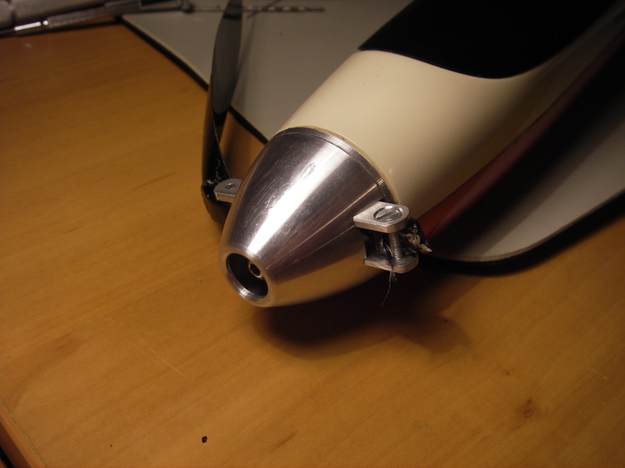
The second flight was less successful.  Immediately after launch it pitched down and hit the runway resulting in two snapped prop blades and cracked stabilisers.  This was probably caused by shifting the centre of gravity forward without removing the tail trim to compensate.
The worst part was that this happened immediately after my supervisor arrived.  This created some scepticism around the story of my first flight, which was not helped by the lack of video (again).

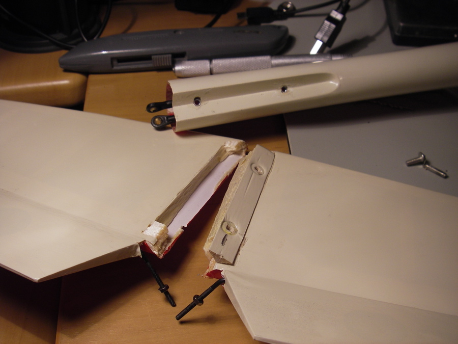
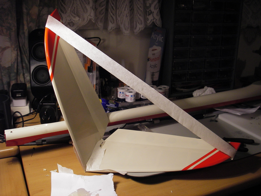
So another night was spent at the workbench putting things back together.  I’m a little relieved that I had the chance to improve the strength in the stabiliser joints.  There was not much force involved in the crash, so they could just as easily have snapped off in the air during a hard pull-up.
I’ve also ordered new blades and a handful of other things from Esprit Model.  They get a special mention as they shipped my parts within 4 hours of me ordering them and their prices are always pretty fantastic.
So the repairs are done, I’m just waiting on the new prop and should be back in the air sometime next week, hopefully with a working camera.

Paprika’s Maiden Flight

It Flies!  After a bit of foul weather recently we lowered our standards and took the Paprika for it’s maiden flight this afternoon.  The sky was a little grey and there was a stiff breeze about, but at least there were no hailstones.

After a last minute check of the surface trims and the flight modes I had set up followed by about 10 minutes staring at the sky and observing the wind to look for an excuse not to hurl my fragile pile of work into it, I was ready(-ish).  With a short sprint down the runway, my supervisor did the hurling as I waited for the moment I had control.
The initial climb was as expected in that it went up in a less than straight line.  The first thing I noticed was the sheer power I had available.  It easily climbed vertically at about one third throttle.
After gaining some altitude, I levelled off to assess the balance and trim,quickly realising that it was far from perfect.  The paprika wanted to pitch the nose up all the time which lead to repeated stalls, stalls that I would not call graceful.  So half the flight was spent helplessly tumbling out of control.  This was were the excessive power I had came in handy.  A short burst of throttle would pull this aircraft out of any tumble with ease giving me back control.
This aircraft takes far more concentration than the Hurricane40D I’ve been flying so far.  So much in fact that I didn’t dare move my thumbs from the joysticks to adjust the trim as it would almost instantly try to backflip.
Eventually one tumble took me so close to the ground that I decided to cut my losses, level out and ditch into the long grass.
I was hoping to catch this flight on video from the plane itself and had attached a small camera under one wing.  Unfortunately I interpreted it’s blinking LEDs exactly wrong and ended up turning it off just before the flight, and back on again when it was back on the ground.
I was also expecting some useful data out of the ESC (Electronic Speed Controller) regarding the motor’s performance but I only have a couple of flat plots consistent with it sitting there doing nothing, which I’m guessing means I need to clear it before each flight.
I guess I’ll just have to fly it again.

Overall the experience was quite exciting and I was certainly shaking at the end of it.  The aircraft is still in one piece, which classifies a successful landing despite collecting a few grass seeds.  It is a completely different beast from the Hurricane40D and there will be a few more exciting flights before I have it under control.
Thanks to Uwe, Florian and Pat for their work behind the cameras.  I’ll add more of their handy work to this post as it comes to me.

Meet the Paprika

Another long absence ends as I’m done with the crappy business of moving house.  Luckily have something new to talk about 😀

This is my new plaything that has recently eaten up all of my time and money.  It’s called a Paprika (AKA Gem) and is the RC glider I’ll be spending a lot of time with over the coming months.

Some stats:

Wingspan: 2m

Weight: 1.515kg

Wing Loading: 4.23 kg/m^2 (13.86 oz/ft^2)

Length: 1.2m

Airfoil: MH32

I’ve gone well overboard with the power train starting with a 100A Speed Controller and ending with a 12×6 folding prop.  In the middle is an 850W Hyperion Brushless motor which will easily be capable of vertical climbs.  The rational of course is efficiency.  I expect the most efficient state for this aircraft will be when the motor is off and the prop has folded back, so the quicker the climb the sooner I can get back to gliding.  This glider won’t actually be the most efficient aircraft it can be, but it will give me plenty of flexibility to try things.

I’ve upgraded my old 36MHz radio to a very snazzy Spektrum DX8.  This thing is incredibly complicated compared to the old 4 channel with mechanical trims.  It does include a telemetry module to keep me updated on the numbers onboard the aircraft which is nice, but it’s gonna be weeks before I wrap my head around how all the other features will benefit me.

I also have some other toys, including a camera and some solar panels.  I’m not expecting fantastic results from either of them, but they will hopefully be enough to inform some avenues of research and of course more money spending.  I’ve also picked up a cheep EeePC to act a ground station.  For now it will just be downloading ESC logs and video recordings, but eventually I’ll have some kind of interface to the auto-pilot I’m in the middle of building.
Maiden flight will hopefully be early next week – weather permitting.

Victory!

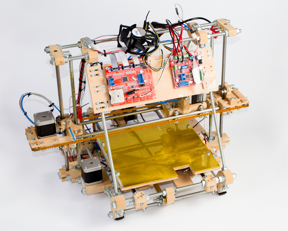
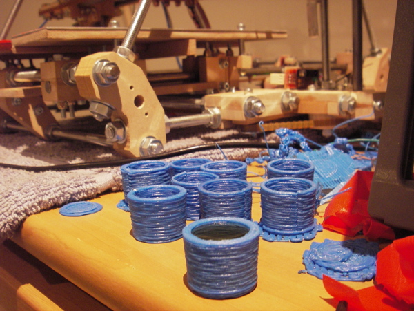
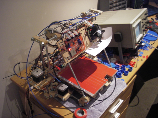
Well it’s been a very long 12 months, and I’ve spent way more cash then I intended but my Mendel is finally capable of printing stuff!  Most importantly: booze proof stuff!

I’ve been obsessing with it over the past week to tweak all the various knobs in such a way that the parts come out neat enough to actually be water-tight, which has been my success criteria the whole way along.
The extruder was an absolute pain, but I’ve managed to hack it together enough that it actually runs quite reliably, just a bit slow for my taste.  I’m working on a geared extruder as I type.
I also had heaps of trouble getting parts to stick, and stay stuck to the printing surface.  So I hacked together a heated bed.  It does very well at being warm and not catching fire, but I’m only pumping 30W into it.  While this helped getting things to stick, it doesn’t stop larger parts warping and lifting off.  So this weekends job is to bump that up around 100W.
I have a lot more detail to go into about these various things, and I know at least one of you is waiting on some source code (I’m getting to it :P).   I’ll save these for future posts once I have some complete comments to make, rather than half finished ideas.
In the mean-time, Cheers! 🙂

Just some updates

It’s been a while since my last post.  This is because I’m halfway through several projects and I’ve been trying to actually get something finished to write about.  Failing that, I think I’ll bundle a bunch of updates into this post.

RepRap

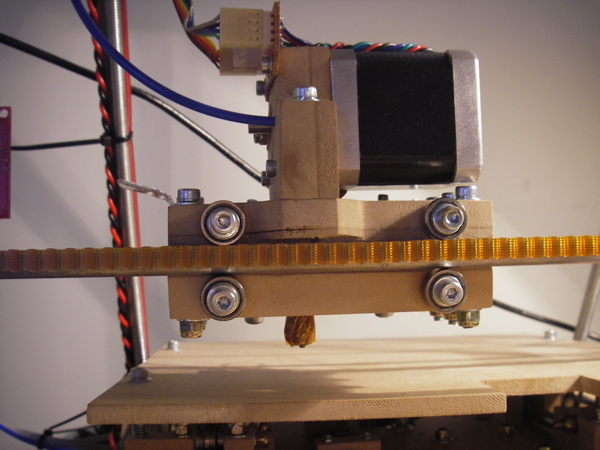
The extruder fitted to the printerKapton tape finally arrived on my doorstep the other week.  This has allowed me to complete the extruder, giving me a complete Mendel! 😀 It appears to work in that it gets hot enough to melt the plastic I poked it with…  I’m not really sure how accurate the temperature measurement is, as MakerBot doesn’t provide any technical data about the thermistor they stock.  So providing the right temperature tables is a bit tricky.
Now I’m spending my time working out the various software tool chains available.  The main choice is between the RepRap host software and ReplicatorG.  I played around with each of them a little and their associated firmware.  The main difference between them is that the RepRap software implements a 5 dimensional G-Code interpreter where ReplicatorG controls the tool speed directly.  The 5D GCodes are much closer conceptually to the actual outputs of the printer, and I see that as the better method.  However, the RepRap implementation leaves a bit to be desired.  ReplicatorG is based on Processing so the GUI is much more stable and intuitive.  I also found the firmware, while it has less features, is also a little more robust.  So I’m ‘moving forward’ with ReplicatorG, and will likely have a number of contributions to make.
The main thing ReplicatorG is missing is support for the Mendel, as it’s primary focus is the CupCake CNC.  The work around to get the stepper extruder working with the 1.x build wasn’t very satisfying.  I’ve added support to the 2.x branch and it seems to work.  Unfortunately, early in my experimenting with the firmware, one of my H-Bridges exploded rather spectacularly leaving my printer crippled.  A replacement will be arriving tomorrow so I can do some proper testing.  I’ll put my code up along with some explanation and howtos once I’ve tested and figured out a working Skeinforge profile.

Servo

I think it’s looking realistic enough now that I’ll give it a short mention here.  I’ve been working on a new servo design intended to fit in the very thin wings of a scale glider.  The main design goal was to keep it under 6mm thick, which I’ve managed to do.  Depending on a few remaining design decisions, I think I can get it down to 5mm thin.
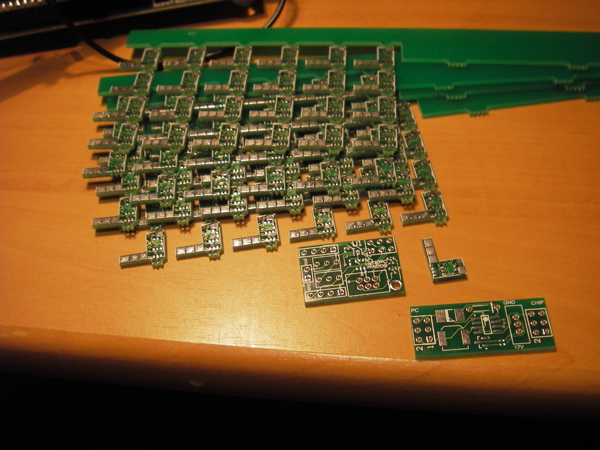
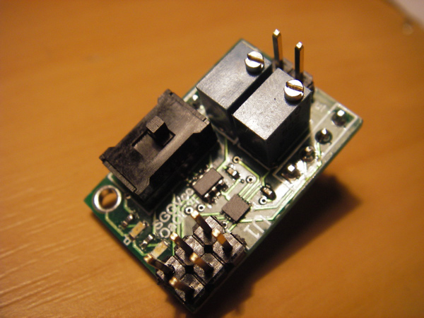
The development version of the servo controllerThe prototype PCBs arrived this week which I was very excited about.  I have Ben at Nias Digital to thank for getting them manufactured.  I’ve populated one of the broken-out versions so I can start testing the firmware.  This involved a lot of time with a scalpel and a pin followed by some frying pan reflow due to my lack of expensive equipment, and the need to use 0402 sized components.  It came out well however, and initial testing has been positive.
More on this one later 🙂

Research Poster

For those of you who don’t know, I’m actually a PhD student at the Australian National University researching Energy Based Planning and Management for Unmanned Aerial Vehicles.  Given I haven’t mentioned this here before, I think that’s most of you.
Each year the College of Engineering and Computer Science hosts a ‘poster day’ where research students can show off their projects.  So I spent the last week creating my masterpiece.  I’ve only been at this research thing for three months now, so my ideas are still a bit… ‘unspecified’.
So here is my poster in all it’s glory! Enjoy 🙂

It Lives!

So I spent the last week removing RJ45 connectors from my electronics.  Aparrently the requirements for the Mendel are quite different than the Darwin, which was the goal back when I put them together.  So after reparing all the tracks I lifted from the PCBs removing things, I laid out the cables around the machine and tied them down.  I think I’ve done a rather neat job.
I also had to setup the end stops, which I haven’t really calibrated yet.  They’re close enough without anything colliding which will do until I’m ready to try printing.  I used some 18 gauge aluminium sheet for the triggers which was easy enough to machine and soft enough to adjust later.
I grabbed the latest software and firmware from SVN and after a bit a fiddling I managed to have it all working from my macbook.  The biggest problem is the RXTX library for serial communication.  On 10.6 machine, the 32bit version won’t work so you either need to compile it yourself, or just grab it from this guy.
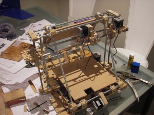
The extruder isn’t finished yet and I’ve ordered a replacement belt for the Z-axis, but here it is!  It’s not actually printing anything, but everything up to that point seems to be working swell 🙂

I have ALL the parts!

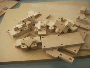
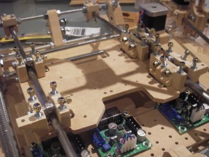
Some more progress last night 🙂  I’ve managed to make all the ‘printed parts’ from wood now, finishing the extruder last night.  As a reward, the universe also delivered the final shipment of parts from MakerBot this morning.  So I’m very close to having a complete, working Mendel :D.
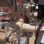
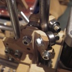
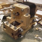
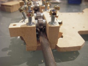
First some shots of the Z-Axis bearing mounts, which I forgot to post weeks ago when I made them.  They were pretty tricky parts to carve, and the grain of the wood isn’t ideal for the loads they’re supporting.  So these are pretty high on the list to replace (as with the majority of parts :S).

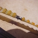
The timing belts also arrived the other week and I’ve finally gotten around to building a splitting jig.  It’s amazing how easy these things are to come up with when you have decent software, and can print templates to scale.

Some of the belts are supposed to be ‘ended’ as in they’re not complete loops.  Unfortunately I cut the wrong one and had to rejoin the ends.  Luckily the belts I bought have steel cable reinforcement, so it was just a matter of scraping off the rubber, cleaning the cables, and soldering them together (using a LOT of flux).

…I’ll probably replace it the next time I order from Small Parts.

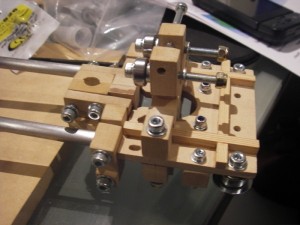
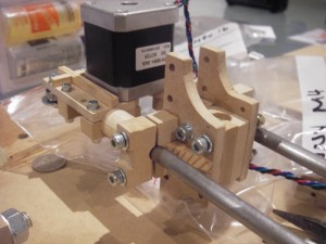
Finally, here’s some shots of the complete extruder carriage.  The extruder itself just needs the nichrome, thermistor and kapton tape attached.

So no more carving to do.  Which I am very relieved (and proud) about.  It’s about time I start looking for that celebration scotch 🙂

Flying

So the ‘final sprint’ I had anticipated has been more of a ‘sit and wait for parts’.  Belts arrived today and my epoxy gears don’t really seem adequate anymore.  I’ll probably make some new ones using the belt as a mould.  I’ve also just sent off an order for the last of the bits I need from MakerBot, so hopefully not too much longer…
I’ve also been working on some super secret new idea that I’m not going to reveal until I know it’ll work 😀 more on that later.  In the meantime, here are some shots of my plane from the other weekend.  Actually flying this time!  Thanks to Jan Zimmer for these.

More Progress – Now a Sprint to the Finish!

My Mendel is still progressing.  I’ve recently completed the Y-Axis including the bearing mounts, chassis and print surface.  The bearing are a little tighter on the rails then I would like, probably due to my laziness drilling the slots to allow for their movement.  It’ll do until I print replacements.

I also made the nut-jigs and nut traps the live on the ends of the X axis, so I can finally assemble them.  I do still need to make the 360 bearing mounts.  These bits are pretty tricky.

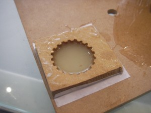
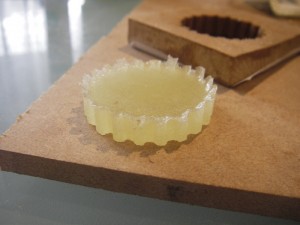
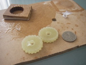
And finally; I’ve also made the driven gears for the bottom the lead-screws.  I surprised myself with these.  I certainly didn’t plan on making them when I woke up.  I was considering making them from MDF like everything else, but decided they wouldn’t last very long.  Instead, I ended up cutting a gear shaped hole, smothering it in vaseline (bear with me here) and then filling it with epoxy.  I had very little expectation that this would actually work.  MDF isn’t the greatest mould, nor is epoxy the greatest thing to mould.  The results were surprisingly good!

The usual technique is to use a length of belt around the inside of the mould to ensure the tooth profile matches.  I don’t have any belts yet so I’ve just used the template amongst the reprap parts.

I did just order timing belts today from Small Parts and Bearings.  Their site is a little tricky, but I managed to get all the belts I need for about $45 including shipping.  I’ve also got my order loaded from MakerBot to get some nichrome, thermistor, end-stops and most exciting of all: actual plastic! 🙂  I plan to find a local plastic manufacturer for a longer term supplier.  Complete Plastic Welding Supplies look to be the best (only?) option.  But my first batch will be a sexy blue Mendel :).  I still need kapton tape, which a mate of mine says he can give me.

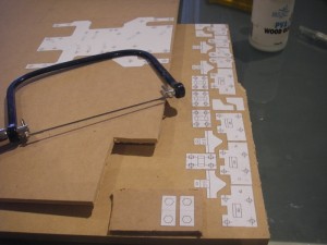
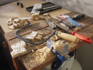
So all those bits are on their way, I just need to cut the final RP parts.  I’m going to attempt all of them from MDF and have prepared all my stencils.  Hopefully I’ll have them all done by Sunday afternoon, coping saw induced RSI permitting.

Some Retroactive Justification

For some reason I’m up rather early this morning.  Having done all the prep work I needed last night, I have nothing to do but wait until a time I can start banging away without disturbing my neighbours.  So I figure this is a perfectly good time to come up with some justification for why I’m going to all this effort.
Ideally I would have gotten all these parts printed by some kind RepRap owner for a case of beer or similar trade.  It quickly became apparent that the effort required to print these parts is enough to turn most generous folk away.  The next option was to have the parts printed by a commercial service.  The cheapest I’ve seen has been Shapeways who have a number of materials to choose from.  The most appropriate for RepRap parts is the ‘white, strong and flexible‘ which currently costs $1.50 US per cubic centimetre.
While this may sound cheap (in fact it’s quite reasonable given the quality of the parts produced), this spreadsheet (webpage) illustrates the actual costs involved in a complete set of RepRap parts.  I’ve used SolidWorks to calculate the volume of each part.  The green and yellow indicated which parts I’ve cut from MDF already, or already have plans to, respectively.
After looking at these numbers I feel pretty justified :).  But what about all the money I did spend on tools and materials?  Well so far I’ve saved around $1300 US making the parts myself.  I’ve definitely spent a few bucks on tools and MDF, but I’ll admit I haven’t really been tracking it very well.  A rough estimate of the tools and materials related specifically to the printed parts (not including fasteners and electronics etc.) would be around $250-$300 AU.  The biggest purchase being a drill-press, which I shall cherish for many years to come.  Of course I’ll still have all my tools long after this project is finished.
Finally; just so I don’t justify my RepRap itself out of useful-ness,  there is a lot of effort involved in cutting each of these parts by hand, and the few parts I have remaining are going to be quite difficult.  So while I’m arguing against spending thousands of dollars getting bits printed, the actual process of 3D printing is way easier than the alternative!  Hopefully the price will someday reflect this.