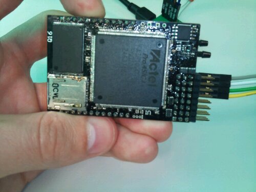
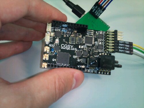
I’ve been a bit slow testing my Cormorant prototypes over the last few months. I have managed to complete the drivers for the IMU sensors and the data radio which cover most of the important hardware devices, so I thought now would be a good time to measure the power consumption. This is not just one simple number however, as Cormorant has many peripheral devices with many configurations each consuming different amounts of power.
Cormorant. A New FPGA Based Autopilot
It has been a few years since I first assembled a prototype flight controller built around an FPGA, having been thoroughly distracted by work and thesis writing it’s about time I updated the design. So I hereby present Cormorant!
The concept is the same as before: motion sensors, actuator control, communication and of course the FPGA. All of these have come a long way since my original ProASIC3 design, and CPU/FPGA “SoCs” have become common. This new design centres around a SmartFusion2 SoC which uses the FPGA fabric of an igloo2 paired with a Cortex-M3 CPU.
Processing Architectures
So I was listening to a recent episode of The Amp Hour; “An off-the-cuff radio show and podcast for electronics enthusiasts and professionals“, and Chris & Dave got onto the topic of custom logic implemented in an FPGA vs a hard or soft core processor (around 57 minutes into episode 98). This is a discussion very close to my current work and I’m probably in a very small minority so I figure I should speak up. (more…)
New Avionics
I recently completed building the first of my new version of Asity, the avionics I plan to use in all my UAV activities. The main improvements in this version are the new inertial sensor chip I’m using. I previously had a separate accelerometer and gyroscope. Now I’m using the MPU-6000, which does both much better than what I had. It also does some motion processing of its own which I am dubious about, but I’m going to try it out and see if it can save me writing my own.
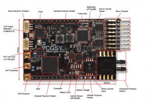
There are also a number a bug fixes I noticed while playing around with the last version. These are silly things like not including a bias inductor on a powered GPS antenna, supplying the wrong voltage to my compass, and forgetting to put decent pull-up resistors on an I2C bus or two. Fingers crossed that there aren’t more I didn’t find.
The most significant improvements are from a manufacturing view. Given that I’m assembling this by hand with a frying pan, I need to put some effort into the design to make it as easy as possible. This involved swapping a bunch of 0402 sized capacitors & resistors for their slightly larger 0603 versions. I also had to consider how I can fix things as I assemble it, so trying not to block access to my soldering iron. I also have a planned out assembly procedure that involves testing at a few stages. It’s much easier to fix some things before the board is complete, so I try to make sure it all works before continuing. Applying solder paste tends to be the messiest part and results in lots of tiny conductive balls rolling around your components if you do make a mess of it. I ordered some Kapton stencil from OHARARP to make this easier.
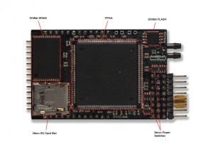
The bottom side of Asity is all hand soldered, so I made sure to choose the components and their layout wisely. This means: no 0402 sized components; no packages with hidden leads (QFN, BGA), and; everything nicely spaced so I can get my soldering iron between things. This last point may have been neglected a little, mostly because there isn’t enough space on the board.
I took two attempts to solder the FPGA on the bottom. The first time was a bit of a nightmare and I spent way too long poking at it with the iron to clear shorts etc. I decided that I had probably butchered the chip and that I didn’t really want it flying my aircraft. So I removed the first one completely, cleaned the pads and started again with a fresh one. It wasn’t a cheap part, but given the components on the others side aren’t particularly cheep either, and they were already working, I decided it was for the best. The second FPGA went on with much less fuss and also seems to work fine now.
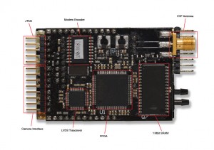
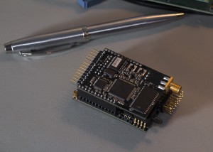
I’ve also assembled the daughter board that fits on top of Asity onboard the aircraft. This board includes a VHF radio to act as a backup link if the main UHF fails. It also has an interface to the camera in the nose of the aircraft as well as another FPGA and some RAM to process images data.
So far everything has tested well. I haven’t tried the radios yet, as I still need to assemble the other end of the link, but I’m feeling pretty confident about everything else. It all fits together nicely (there’s a massive radio module sandwiched between the two halves) and only weighs 53g assembled. Now I just have to fill it with useful code.
Research Poster… Again
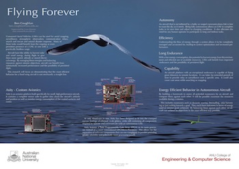
So it’s that time of year again where all of us graduate students here at the College of Engineering and Computer Science are made to produce posters for our projects.
My effort from last year is still available over here if you were interested in comparing the two.
The concept remains the same, but this year has a few more updates on the direction of my research and some pretty pictures of Asity. The albatross is still around.
So with that out of the way, I’ll get back to doing some real work 😛
Pan/Tilt Prototype Underway
I managed to convince myself that pursuing my pan/tilt design was a good idea. The design itself is complete and I have sourced all the parts I need. Some parts have already started arriving.
If you don’t know what I’m talking about, or would like to fit the parts described below to the design then you can find the details here.
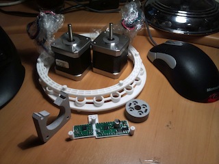
The parts from Shapeways arrived today. Shapeways is a 3D printing service, an activity I had hoped to achieve with my ill-fated RepRap. I’ll fix it one day… Anywho! Shapeways prints much finer things than a RepRap is capable of and offers a few more choices of material.
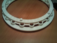 The big white circle is the bearing that the whole pan/tilt mount sits on. It takes the weight while still allowing it to rotate. Given it’s relatively large diameter, it should keep everything stable.
The top and bottom part mate with the steel base plate and the main chassis while providing a groove for some steel balls to roll in. The middle is a spacer to keep the balls evenly spaced.
The whole mechanism is held by a central bolt which clamps the two halves together against this bearing.
This is Shapeways laser sintered plastic. It can be pretty strong if you don’t make it too thin. I’m very happy with the accuracy of the print. Remind me to go back and tighten the tolerances in my design.
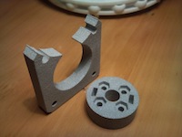 The squareish part on the left here is a motor brace. It fits between one of the motors and the chassis to allow space for gears to turn.
I made the decision to place the ’tilt’ gears inside the chassis rather than on the outside face. This is for a few minor reasons including aesthetic, symmetry and safety. This way both outside faces are flush and there are no exposed gear teeth to byte hapless fingers.
The round part is a locking hub, supposed to bolt to the face of a panel and lock it to a shaft with two set-screws.
This kind of part is surprisingly difficult to find for a reasonable price and in the right size. I managed to find some imperial sized bits that are ‘close enough’ from ServoCity. This printed version is just in case I can’t use the steel ones.
Both of these are printed in alumide; a combination of the plastic above and aluminium powder. Not quite as strong as the plastic but much harder. The motor brace will work fine but I am skeptical about the locking hub. Fingers crossed those ServoCity hubs are suitable.
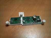 The last piece I’ve ordered from Shapeways is a PCB bracket. This bolts onto the chassis and holds the controller PCBs for the pan/tilt mount.
I may have made this a little bit too skinny. It was one of those situations where it looked fine in CAD on my computer and I failed to realise just how small it really was.
This one successfully holds the PCBs but it does do so under some tension. I think it’ll be fine to make the prototype work, but I’ll probably replace it with a sturdier version at some point.
The actual PCBs I’m using are pretty straight forward stepper controllers from Little Bird. Thanks to Madeline at Little Bird for adding them to their catalogue after my nagging.
These use the A4988 controller which allows 2 amps per motor coil, provides a very simple interface and allows up to 1/16th stepping.
The breakout boards will suffice for now, but if I decide to make lots of pan tilt mounts I will probably make my own boards to go with it.
The remaining parts to order include numerous nuts & bolts as well as the rather important steel parts. I’m actually getting the steel parts laser cut and bent for me. It’s not cheap, but it saves me struggling to form steel plate in my backyard. Hopefully I will have a completed prototype in late June.
Asity Scores a GPS Position Lock
Today I was relieved to get some GPS data out of my Asity prototype(s). Since assembling one the other week there have been a few set backs, but as of this news I’m still on track.
The first one I made did seem to work at the time, however the FPGA has since stopped working. It seems it has lost the ability to write program data to its internal FLASH and nothing I do seems to make a difference. It appears the fault is completely internal to the chip and I’m putting it down to my shoddy assembly, it was on a frying pan after all.
To keep things moving I decided to build the second prototype. I had always intended to build two; the second being a stripped down version including only the sensors needed to operate the antenna tracking on the ground, as well as the radio.
This second board was much neater having learnt some lessons from assembling the first. The FPGA works and accepts my code without issue. However I found the GPS was not functioning. After checking all the solder joints I still have no idea why…
Eventually I resorted to mangling the two half working boards in to one fully functional board.
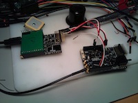
This was simply a process of balancing leads on the data pins of the working GPS and hooking them up to some of the servo signals on the other board (I love FPGAs 🙂 ). This worked as expected and I was able to talk to the GPS. However I was unable to get a position lock from it.
After pondering a while I gave a mate a call who I usually turn to in times of such technical conundrums. He was surprisingly quick to point out that I was using an active antenna but not actually supplying any power to it. It turns out I had completely missed the required inductor between VCC and the GPS’s RF line.
The datasheet for the GPS in question suggests a 33nH inductor is used to bias an active antenna. These are quite a lot smaller than the usual components found in labratory stock, and certainly not something found at the local electronics store. Being impatient, and unwilling to order a bunch of stuff to fill a shipment for a single inductor I decided to improvise.
After ‘jumpers’, inductors are the easiest component to manufacture yourself. They are just a coil of wire after all. Unfortunately it has been several years since my high school science teacher tried to teach me the maths involved in coiling an inductor. Luckily Google was more than willing to provide an ubundance of inductor calculators.
With some trial and error I picked some numbers that looked reasonable and wound some solder wire around a meter probe. After some more trial and error, I had a coil that was apparently in the right ball park.
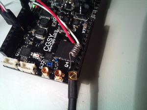 With my home made inductor in place, I was amazed to find that I could actually track some satellites. I’ve managed to find 12 satellites while sitting Asity inside, on my desk. Amusingly they’re all to the northwest which is where my window happens to face.
So the GPS works fantastically (on half of my boards). The faults I have uncovered are not consistent for both boards, other than the missing inductor of course, so I’m still confident I can make this design work.
Asity Lives! ..and it says ‘hi’.
The Asity prototype has been assembled and actually appears to work! 😀
For those of you unaware, Asity is the avionics board I’ve spent the last 6 months designing and intend to use to control my unmanned aircraft.
I spent roughly two days with my solder paste and frying pan assembling it. The order was important as some solder joints are impossible to correct once they are surrounded by components, so I had to reflow the top layer a few times to get everything on. The bottom was completely hand soldered and I’m seriously considering the $400 for a new soldering station with a much smaller tip. After everything was on I then had to spend a very tedious few hours tracking down and correcting shorts. Eventually the meter said it was all good and I powered it up. Thankfully no smoke escaped.
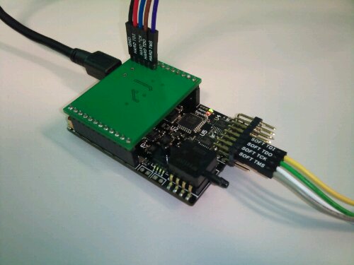 Asity with the USB interface and two JTAG ports attachedThe next trick was to try actually talking to it. I had trouble using Altium’s JTAG adapter at first. There seems to be some signal integrity issue over that header. The solution at the moment is a 10nF capacitor from the TCK line to ground.
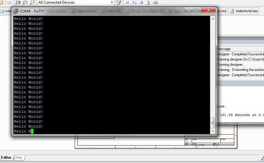
To my amazement I was able to connect to the FPGA and even load some firmware onto it. I started with a simple demo I had made earlier on my Spartan 3E dev board, which repeatedly reads some bytes from a block RAM and sends them to the USB interface. I soon realised that the bit file uploaded to an Actel FPGA doesn’t actually include RAM initialization data, so I found Asity spewing random gibberish at me. After realising this and manually initializing the RAM, I had my demo working.
Tadaa!
My task is now to write the firmware to access all the peripheral devices I included and find out which of those work and which ones don’t. I hope to get at least the GPS working and able to record data to the SD card within a week so I can start logging data from actual flights.
Prototype Assembly
So I’ve been waiting for PCBs since christmas before I could continue building the Asity prototype. My first batch was ordered from BatchPCB and arrived a few weeks ago. Unfortunatly I couldn’t use these for a number of reasons.
Firstly, the quality of the boards left a bit to be desired. The solder mask was misaligned slightly and was often missing between the fine pitch pins of the FPGA. The hot air level finish was also a bit on the bumpy side, and missing from some pads. These would be ok for larger designs, but fine pitch work is hard enough already so I didn’t risk it. I’ve used BatchPCB for two layer boards a few times and had no issues, but I don’t think I’ll use their four layer service again.
Second; the gerbers I sent to be manufactured had a bug in them which shorted one of my power rails to ground. I tracked this down to a bug in Altium, which was quite disturbing. It has been fixed in version 10.
The last issue was my own fault. The footprint for my main power regulator was flipped causing me to kick myself repeatedly.
So I fixed my designs and added a few changes I had decided on during the wait and sent off another order; this time to EastPCB in China. Their website reeks of template and does seem a little ameturish but their quote was significantly below any other manufacturer, so I decided to give them ago. After two weeks, the boards arrived yesterday and I’m thrilled with how well they turned out. I chose an immersion tin finish which is much neater than the hot air level on the last boards. The solder mask is perfect on both sides and a much sexier black instead of the standard green. As a bonus, they didn’t remove any of the letters on my overlay unlike some others… It’s nice to have the rev number printed on the boards. On top of all this the order came back with a full test report and cross section sample taken from my production run.
I spent this afternoon assembling one board. I haven’t made it easy on myself with the spacing between components, but I’m confident it can all be done on a frying pan. It will just require a few bakes to get all the parts on. The power supply and watchdog went on today and everything is working perfectly which I’m thrilled about. At least now I know that if there are other issues on the board, they will be isolated to a particular component and I can still use the rest.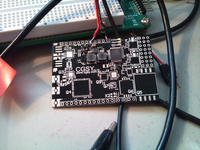
Turns out I ordered ADCs with the wrong footprint so I’ll have to take a break while I wait for new ones to arrive. Hopefully I’ll have it completed by the end of next week.
Seeking Sponsorship for the Outback Challenge
So I have decided that it would beneficial to my research and the development of Asity if I attempt to enter this years Outback Rescue Challenge.
I have completed the preliminary designs, costings and schedule and with a lot of help I might actually have a capable aircraft by September.
Given my hands are pretty full completing the software to run on Asity, I am enlisting the help of an undergraduate Software Engineering team to help build (or extend) the software for a Ground Control Station. I presented my project to them this morning and with any luck I should be meeting a capable team in the next week or so.
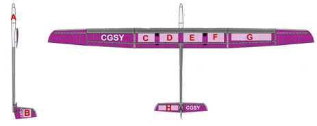
I am now appealing to the masses for help funding this endevour. If you know of anyone who runs a business providing products or services that are relevant to UAV research, the expected audience of the outback challenge, or are just really really nice; please point them towards me. My current plan is to allocate space for sponsors on the actual aircraft where they can place their name and logo like so:
The money raised will be used to purchase the aircraft itself, manufacture custom hardware and cover things like travel, accommodation and insurance.
I can be contacted at ben.coughlan@cgsy.com.au
