Controlling Zynq PL Clocks in Linux Userspace

The Xilinx Zynq Ultrascale devices seem to have this covered, but I struggled to find much info on how to do this with the Zynq 7000 parts.  Here’s my notes on both platforms.

With a 4.19 kernel, the Xilinx PL clock enabler (XILINX_FCLK) is the driver you need.  This will expose any compatible = “xlnx,fclk” device-tree nodes to userspace through sysfs.  On Zynq this is something like

# echo 150000000 > /sys/devices/soc0/fclk0/set_rate
# cat /sys/devices/soc0/fclk0/set_rate
142857142  # obviously some PLL rounding to deal with

on ZynqMP

# echo 150000000 > /sys/devices/platform/fclk0/set_rate
# cat /sys/devices/platform/fclk0/set_rate
133333332  # obviously some PLL rounding to deal with

The ZynqMP dtsi’s already have fclk nodes supplied from zynqmp-clk-ccf.dtsi.  My Zynq dts didn’t (probably because it was branched many years ago…) but they can be added like:

fclk0: fclk0 {
    status = "okay";
    compatible = "xlnx,fclk";
    clocks = <&clkc 15>;
};

The PL clocks on the Zynq are <&clkc 15>, <&clkc 16>, <&clkc 17> and <&clkc 18>.  On the ZynqMP they are <&zynqmp_clk PL0_REF> etc. (if you #include <dt-bindings/clock/xlnx-zynqmp-clk.h>).

If you don’t want to set clock frequencies from userspace, you can use ‘assigned-clocks’ in any device tree node that seems relevant.

&custom-thing {
    assigned-clocks = <&clkc 15>, <&clkc 16>;
    assigned-clock-rates = <250000000>,
                           <100000000>;
};

Hope this saves someone else some time.

Custom ISR Prologue in AVR C

I fell into a situation recently where I was relying on pin change (PCINT) interrupts to decode a serial protocol. This meant I needed to be able to detect if the interrupt was triggered by a rising or falling edge. This particular protocol can have pulses as short as 1uS (8 CPU cycles) so in order to tell if the pin was rising or falling I need to sample it within 8 cycles of it actually happening. Adding time for the pin synchroniser and a non-detirministic ISR entry up to 7 cycles-ish, by the time the ISR starts you’re usually already too late… won’t stop me trying though!
(more…)

Ubuntu on IGEPv2

Preface

This is a short guide to getting Ubuntu running on the IGEPv2 Rev C from a bootable SD card.  There are a few guides around that I’ve based various sections on, but I couldn’t find a complete howto that was up to date with the current hardware.  Most credit goes to Michael Opdenacker of Free Electrons.

(more…)

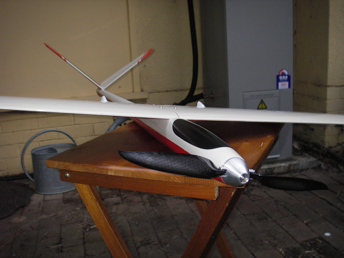
The Pulsar’s Maiden Flight

So it’s been 18 days short of a year since the Pulsar arrived in a giant box.  Since then there has been a lot of time spent measuring and modelling and generally designing to figure out how to fill it with stuff to ready it for the outback challenge.

It took a few attempts at various components to get the fit right.  Measuring its sleek, sexy curves proved to be quite difficult.  The last few days have been spent shifting things around to perfect the balance and program my recently replaced radio equipment. (more…)

DSM2/DSMX Remote Receiver Protocol

I’ve been playing around with my transmitter a lot recently as flying season is starting up again and the darn thing isn’t working well.  Likewise, the receiver I’ve just installed in the Pulsar refuses to bind to my radio.  So a big fail all round by Spektrum, which has lead me to seek alternative solutions.

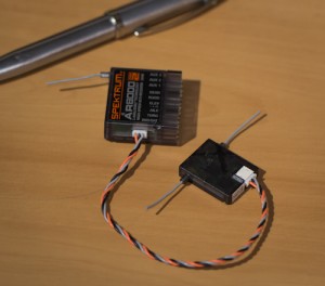
The AR8000 Receiver with a remote receiver attached

I’ve seen a few forum threads discussing the serial protocol used by Spektrum’s remote receivers and it seems pretty straight forward to collect the data from them; bypassing the main receiver completely.  Unfortunately the only decent write up of the details that I could find was a bit out of date, and only covered the 7 channel case.  So here is what I’ve learnt from poking this device with an oscilloscope and a logic analyser for a few hours. (more…)

Pan/Tilt Prototype is Complete

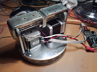
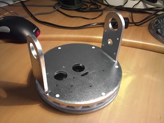
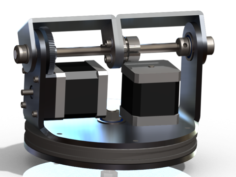
The pan/tilt hardware for my antenna tracking tripod is finished.  It even looks kinda like my design :D.

With the layer of zinc I didn’t account for, everything is actually pretty tight (after some sanding).  There is no play anywhere except for some slight backlash in the gears.  The mounting brackets don’t slide on the shaft and the chassis doesn’t rock on the main bearing at all.

The unit as a whole is pretty solid and weighs more than my scales will tell me.  My CAD software tells me it’s around 4 to 5 kg.

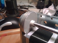
Unfortunately the small gears I received had the wrong bore size.  I couldn’t be bothered having new ones shipped from the US so I decided to drill them a bit larger myself.  This ended in fairly average results.  The gears fit the motor shaft fine, but they have a bit of a ‘wobble’ as they rotate which is less than ideal.  They’ll work for testing, but will be an issue when I put some load on them.  Some new gears from a local supplier are on the way.

The bends in the metal were off by a degree or two.  Not much, but the very tight tolerance on the shaft mounts mean that if the holes don’t line up then the shaft jams when I try to assemble it.  This was solved with my trusty sledge hammer, which was odd given the 0.05mm tolerance.

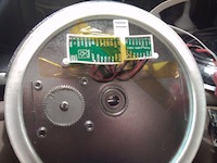
The electronics and their mounting are probably one aspect I put the least thought into.  I’m just using the Pololu A4988 controllers and mounting them in a very flimsy plastic frame.  It’s not my proudest moment, but will work for now.

I’d actually like to make my own board at some point.  The Pololu controllers are a bit pricey compared to the chip that actually does the work.  They also won’t easily accommodate a heatsink.  Without the heatsink I can only run the motors at about half their maximum power.  My own board would have actual mounting holes and a heatsink making the whole arrangement much neater.

The gears come with an M2 grub screw which is pretty small considering the load I’ll be putting on them.  These tiny screws need a 0.9mm hex key which is very small and not amongst my collection.  It also doesn’t appear in any sets I could find in the shops.

I had a go at tapping a new M3 hole for a bigger, more convenient grub screw.  This pretty much failed as the hole for a set screw is very shallow, and a hand-tapped thread tends to be crappy at the top.  So there wasn’t enough thread for the bigger grub screws.  I’ve decided to order the tiny hex key and see how the small screws go.

Right now I’ve mounted two SLA batteries on the chassis itself along with Asity as the controller.  This should let me play with it, without worrying about tangling cables.  I still haven’t written any software to control it, so no movement yet.

More Pan/Tilt Parts

The main chassis for the my pan/tilt mount is made from 5mm steel plate.  This is a rather difficult material to work with in my garage, so I opted for the services of some professionals with industrial size lasers and presses.

The lasers, as you would expect, are very precise.  All the cuts are spot on.  My main concern was with the bends.  Even with a robotic press, bending thick metals can be a bit unpredictable.  Even so, the bends came within 0.5 mm of where they needed to be.

I took the parts straight to the electroplater across the road and had him put a zinc coating on all the parts.  The process cleaned off all the crumbs from the laser as well as the heat-scale and the zinc made them nice and shiny.  Over all I’m very happy with the finish.

The parts are completely rigid, at least when tested with my puny human muscles.  The structure should be capable of quite a significant load.  The weakest point in the design will be the strength of the motors.  This isn’t an issue if the load is balanced around the rotation axes.

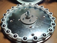
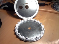
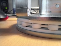
The plastic bearing runs mate with the steel plate of the base and the chassis with six extrusions.  The fit was actually quite tight, but after some squeezing they fit and stay together perfectly.

The steel balls fit the spacer perfectly as well.  It takes a bit of force to insert them, but once they’re in, they stay in while still rolling freely.  With all the balls inserted (I only have 9 at the moment), the spacer is sandwiched between the two runs.  The two halves spin freely on the main bearing and the spacer doesn’t rest on the bottom run.

There is one last package to arrive containing bearings, nuts & bolts.  Hopefully it will be here by the end of the week.

Pan/Tilt Heads for Antenna Tracking

I’ve fallen back into hardware mode before making any significant progress recently.  I have to say I enjoy it more, and I do have so much hardware to come up with for the Outback Challenge.
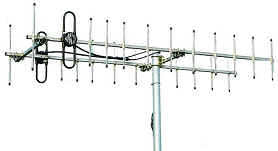
The last week has been focused on antenna tracking.  Basically I have two large yagi antennas that I need to keep pointed at the aircraft which requires a pan/tilt head mounted on a mast.

The antennas are quite large, weighing about 4.3Kg total and being about 2m long. I’d also like the mount to be stable enough to mount a camera with a suitably large lens.  Having something automatically record the aircraft will make documentation much easier.
This puts me in an awkward range in terms of pan/tilt heads. The options either seem too light and under-powered, or prohibitively expensive.

Not considering the tiny, point-and-shoot camera variety; the affordable end of the scale looks to have two serious options (although if there are any out there I have missed I would love to know about them).

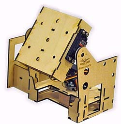
The most popular in the FPV community seems to be this thing, annoyingly unnamed.  Made from laser cut wood it is more than capable of swinging a single patch antenna around, but will definitely struggle under my yagis.

It’s nice and cheap at $90 including servos.

The pan/tilt head closest to my specs is the AT Pro-1000.  This is made completely of aluminium and when using the supplied HS645MG servo on the tilt axis there is plenty of torque, about 9.5Kg.cm.

The main drawback of this design is that it is definitely aimed at patch antennas, with large, wide structural members.  They do provide a bracket for mounting a single, smaller yagi, however getting both of my antennas on there will be awkward.
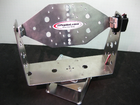
AT Pro-1000The AT Pro-1000 weighs about 1Kg and is roughly 30cm wide.  It’s price point is almost exactly where I am looking at $220 including servos and yagi bracket.

So it seems easy enough to swing patch antennas around.  Unfortunately patch antennas don’t offer the gain or the focus of a large yagi.  Outback Joe didn’t exactly get lost in a convenient place and maintaining comms is pretty critical.

The other end of the scale comes with incredible specs and some pretty fantastic features.  It also comes with a bunch of request for quote forms…
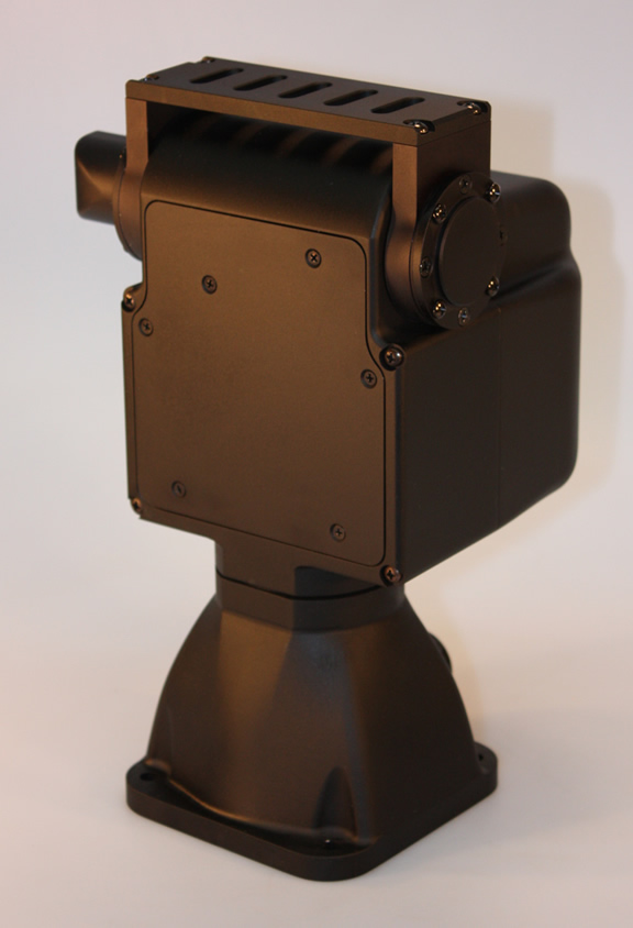
D48ESomething like the D48E or even it’s smaller cousins would easily meet my needs, and then some.

Capable of swinging over 10Kg around at 100 degrees per second (probably not at the same time) and incredible 0.003 degree tilt resolution.

The offerings from FLIR also boast ethernet integrated and all weather operation.

These are actually available from distributers in the US and Canada, but even the smallest was well over $2000.  Far beyond my budget, and requirements for that matter.

The one major difference is the design.  The D48E has more uses in mind than just patch antennas and so only offers a single mounting bracket for any accessories, making it easier to mount custom hardware.

So like most of my product searches recently, I’ve resolved to design and build one myself.  I’d be lying if I said I was disappointed 😛

Over the last week I’ve been madly scheming and searching the interwebs for suppliers and I think I’ve gotten to a draft I can actually build in my garage.

I originally wanted to use 6mm steel plate to ensure it was strong and rigid.  I eventually realised that my tools are not up to steel, especially if I were to try hot-forming the bends.  I considered having someone machine the steel for me but decided that I didn’t really need steel at all.

To simplify things a few orders of magnitude, I decided on 6060/1 aluminium in stock extruded channel.  Aluminium is much easier to work with the in the backyard, and using stock in the right shape meant that my job was already half done.

At the moment I’m trying to decide between servos or stepper motors, and where to find the cheapest parts ($50 for that hub in the middle! seriously!) but the shape is pretty much fixed.  The antennas will mount towards the ends of a bar bolted to the top face.

The base diameter is 150mm and sits completely on a custom bearing, so there should be very little wobble.  I’m aiming to keep the entire cost below $300.
Meet the Paprika

Another long absence ends as I’m done with the crappy business of moving house.  Luckily have something new to talk about 😀

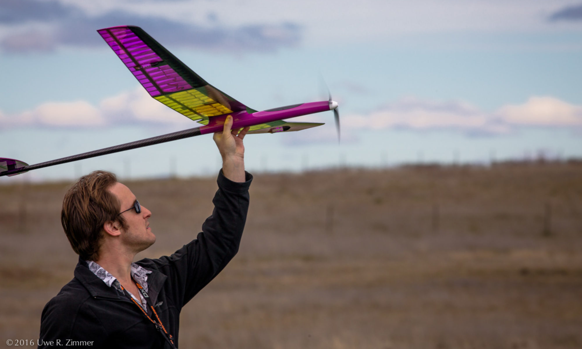
This is my new plaything that has recently eaten up all of my time and money.  It’s called a Paprika (AKA Gem) and is the RC glider I’ll be spending a lot of time with over the coming months.

Some stats:

Wingspan: 2m

Weight: 1.515kg

Wing Loading: 4.23 kg/m^2 (13.86 oz/ft^2)

Length: 1.2m

Airfoil: MH32

I’ve gone well overboard with the power train starting with a 100A Speed Controller and ending with a 12×6 folding prop.  In the middle is an 850W Hyperion Brushless motor which will easily be capable of vertical climbs.  The rational of course is efficiency.  I expect the most efficient state for this aircraft will be when the motor is off and the prop has folded back, so the quicker the climb the sooner I can get back to gliding.  This glider won’t actually be the most efficient aircraft it can be, but it will give me plenty of flexibility to try things.

I’ve upgraded my old 36MHz radio to a very snazzy Spektrum DX8.  This thing is incredibly complicated compared to the old 4 channel with mechanical trims.  It does include a telemetry module to keep me updated on the numbers onboard the aircraft which is nice, but it’s gonna be weeks before I wrap my head around how all the other features will benefit me.

I also have some other toys, including a camera and some solar panels.  I’m not expecting fantastic results from either of them, but they will hopefully be enough to inform some avenues of research and of course more money spending.  I’ve also picked up a cheep EeePC to act a ground station.  For now it will just be downloading ESC logs and video recordings, but eventually I’ll have some kind of interface to the auto-pilot I’m in the middle of building.
Maiden flight will hopefully be early next week – weather permitting.

Just some updates

It’s been a while since my last post.  This is because I’m halfway through several projects and I’ve been trying to actually get something finished to write about.  Failing that, I think I’ll bundle a bunch of updates into this post.

RepRap

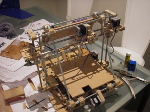
The extruder fitted to the printerKapton tape finally arrived on my doorstep the other week.  This has allowed me to complete the extruder, giving me a complete Mendel! 😀 It appears to work in that it gets hot enough to melt the plastic I poked it with…  I’m not really sure how accurate the temperature measurement is, as MakerBot doesn’t provide any technical data about the thermistor they stock.  So providing the right temperature tables is a bit tricky.
Now I’m spending my time working out the various software tool chains available.  The main choice is between the RepRap host software and ReplicatorG.  I played around with each of them a little and their associated firmware.  The main difference between them is that the RepRap software implements a 5 dimensional G-Code interpreter where ReplicatorG controls the tool speed directly.  The 5D GCodes are much closer conceptually to the actual outputs of the printer, and I see that as the better method.  However, the RepRap implementation leaves a bit to be desired.  ReplicatorG is based on Processing so the GUI is much more stable and intuitive.  I also found the firmware, while it has less features, is also a little more robust.  So I’m ‘moving forward’ with ReplicatorG, and will likely have a number of contributions to make.
The main thing ReplicatorG is missing is support for the Mendel, as it’s primary focus is the CupCake CNC.  The work around to get the stepper extruder working with the 1.x build wasn’t very satisfying.  I’ve added support to the 2.x branch and it seems to work.  Unfortunately, early in my experimenting with the firmware, one of my H-Bridges exploded rather spectacularly leaving my printer crippled.  A replacement will be arriving tomorrow so I can do some proper testing.  I’ll put my code up along with some explanation and howtos once I’ve tested and figured out a working Skeinforge profile.

Servo

I think it’s looking realistic enough now that I’ll give it a short mention here.  I’ve been working on a new servo design intended to fit in the very thin wings of a scale glider.  The main design goal was to keep it under 6mm thick, which I’ve managed to do.  Depending on a few remaining design decisions, I think I can get it down to 5mm thin.
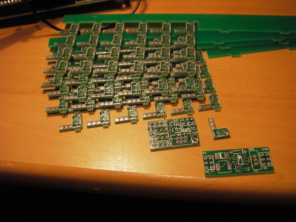
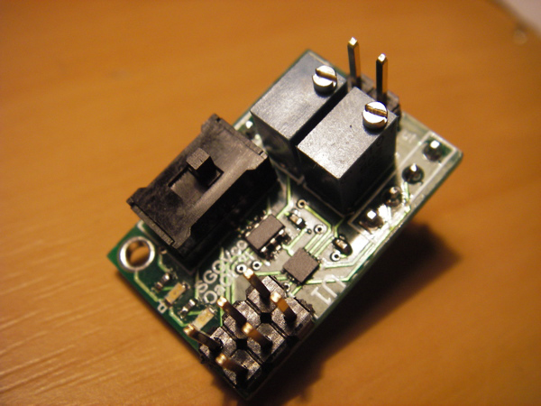
The development version of the servo controllerThe prototype PCBs arrived this week which I was very excited about.  I have Ben at Nias Digital to thank for getting them manufactured.  I’ve populated one of the broken-out versions so I can start testing the firmware.  This involved a lot of time with a scalpel and a pin followed by some frying pan reflow due to my lack of expensive equipment, and the need to use 0402 sized components.  It came out well however, and initial testing has been positive.
More on this one later 🙂

Research Poster

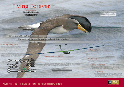
For those of you who don’t know, I’m actually a PhD student at the Australian National University researching Energy Based Planning and Management for Unmanned Aerial Vehicles.  Given I haven’t mentioned this here before, I think that’s most of you.
Each year the College of Engineering and Computer Science hosts a ‘poster day’ where research students can show off their projects.  So I spent the last week creating my masterpiece.  I’ve only been at this research thing for three months now, so my ideas are still a bit… ‘unspecified’.
So here is my poster in all it’s glory! Enjoy 🙂

I have ALL the parts!

Some more progress last night 🙂  I’ve managed to make all the ‘printed parts’ from wood now, finishing the extruder last night.  As a reward, the universe also delivered the final shipment of parts from MakerBot this morning.  So I’m very close to having a complete, working Mendel :D.
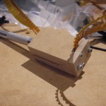
First some shots of the Z-Axis bearing mounts, which I forgot to post weeks ago when I made them.  They were pretty tricky parts to carve, and the grain of the wood isn’t ideal for the loads they’re supporting.  So these are pretty high on the list to replace (as with the majority of parts :S).

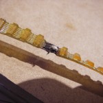
The timing belts also arrived the other week and I’ve finally gotten around to building a splitting jig.  It’s amazing how easy these things are to come up with when you have decent software, and can print templates to scale.

Some of the belts are supposed to be ‘ended’ as in they’re not complete loops.  Unfortunately I cut the wrong one and had to rejoin the ends.  Luckily the belts I bought have steel cable reinforcement, so it was just a matter of scraping off the rubber, cleaning the cables, and soldering them together (using a LOT of flux).

…I’ll probably replace it the next time I order from Small Parts.

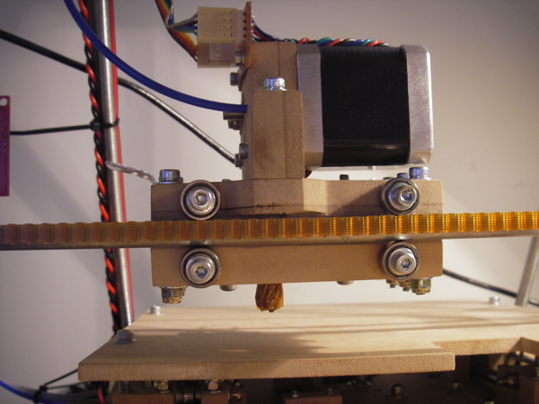
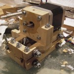
Finally, here’s some shots of the complete extruder carriage.  The extruder itself just needs the nichrome, thermistor and kapton tape attached.

So no more carving to do.  Which I am very relieved (and proud) about.  It’s about time I start looking for that celebration scotch 🙂