So the massive lack of updates recently has been due to me gaining knowledge in the business management and marketing fields. I’ve been doing some more coursework to complement my PhD and make me generally more entrepreneurial. A fairly painful experience so far, and one which will last for another six months.
Between paragraphs of my business plan I did manage to update the designs for Asity as well as complete the CAD models for the parts I need for the Pulsar. This combination is geared towards completing the Outback Challenge while still being useful to my research. So here’s an attempt to illustrate what I’m building.
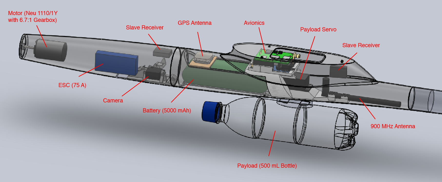
This is the layout of the components I intend to include in the Pulsar4E airframe I’ve got lying around. It include the typical motor-ESC-battery you’d find in a modern electric RC plane as well as the avionics and camera components I’ve been working on. You’ll also notice the whopping great water bottle hanging from the bottom. This is of course the all important payload that needs to be delivered to Joe.
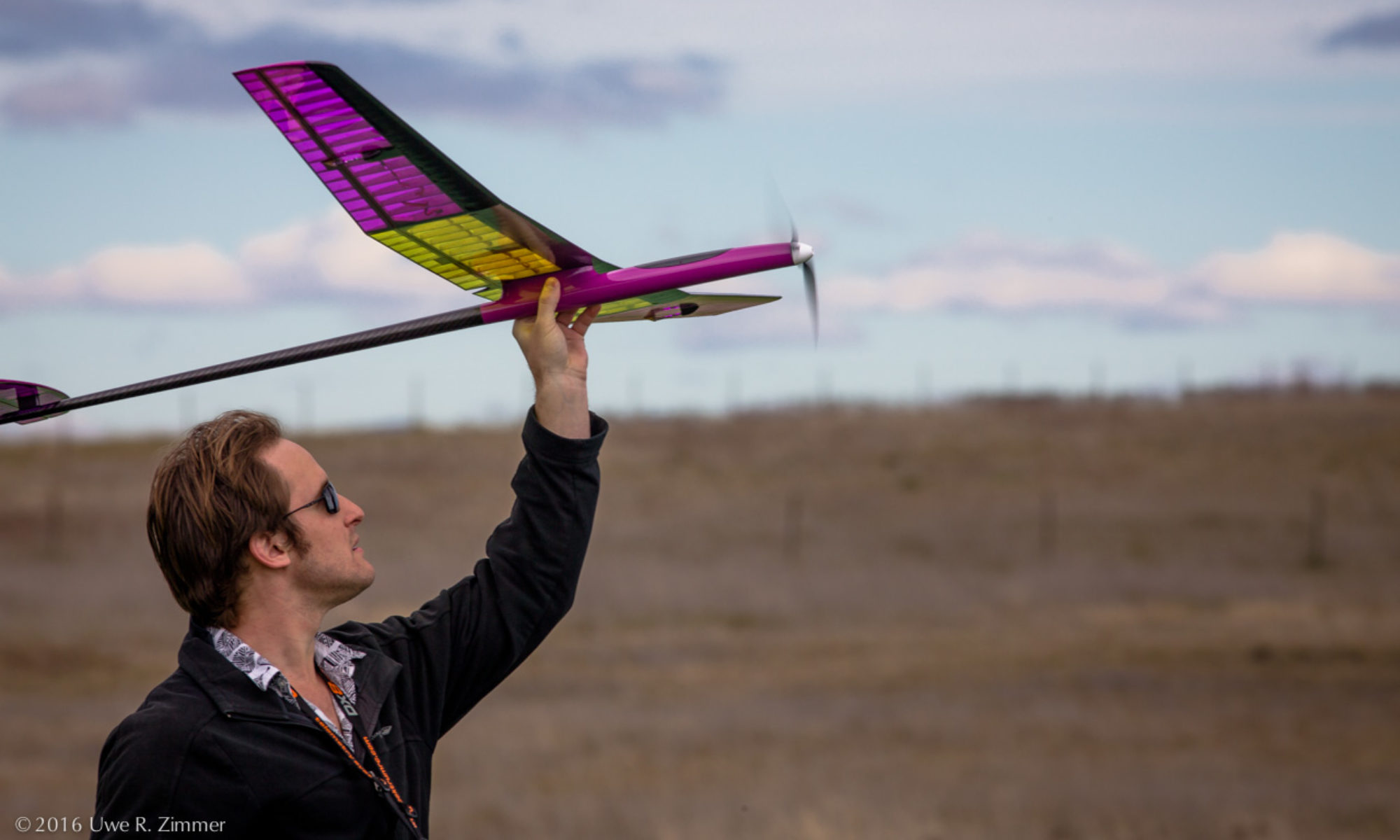
The motor, Electronic Speed Controller (ESC) and propeller blades are being carefully selected to allow the whole aircraft to climb vertically with a payload when the throttle is flat out. Once it reaches a comfy altitude, the motor is switched off and the propellor folds back. I’m using a Neu 1110/1Y with 6.7:1 gearbox with a 75A ICE Lite ESC from Castle Creations. I’ve picked a few props with varying pitches to experiment with. I’m expecting the aircraft’s takeoff weight to be around 3 kg, and so aiming for a static thrust slightly higher than that.
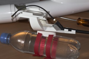 The moulded parts shown are all coming from Shapeways. Results so far are promising. The quality is great and my measurements of the curvy fuselage are actually quite accurate. Not so accurate are the dimensions I chose for the servo components in the payload dropping mechanism, so I will need a few bit reprinted.
The payload is suspended from a pylon by two polypropylene webbing straps. I will also add some velcro between the pylon and bottle to prevent it from sliding back and forth. The pylon fits a hole in the bottom of the fuselage and mates with a beefy servo with a metal horn.
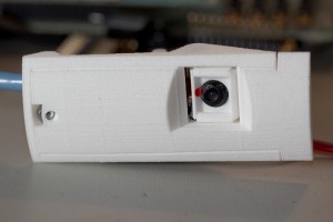 The camera is towards the front of the aircraft and also needs a hole cut in the fuselage. The camera I’ll be using is a fairly cheep 1.3MP CMOS sensor; the kind you would’ve found in a phone from 2005. It should be just enough to spot a vehicle from 1500ft, and hopefully Joe from 400ft. I believe the aircraft will be able to stabilise the camera adequately, so I have only included one servo to compensate for the pitch of aircraft. As I’ll be gliding most of this time, I’ll usually be pitched down and will need to adjust the camera.
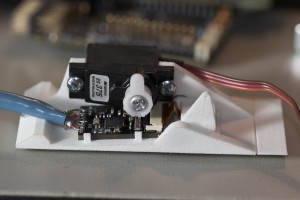 I designed a small board to transfer data from the camera back to the main processors in the center of the aircraft. The board pictured includes a small LVDS transceiver that will translate the parallel interface of the camera into a high speed serial stream, back up the Cat5 cable to a similar chip which will recreate the parallel interface and feed it into an FPGA. From there it will be appropriately processed and fed into the UHF radio to be sent to the ground.
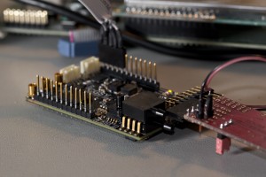
I’ve also built the first of my latest version of Asity; the avionics I’m developing. I’ll go in to more detail about this in another post, so for now here is a pretty picture:
