Today I was relieved to get some GPS data out of my Asity prototype(s). Since assembling one the other week there have been a few set backs, but as of this news I’m still on track.
The first one I made did seem to work at the time, however the FPGA has since stopped working. It seems it has lost the ability to write program data to its internal FLASH and nothing I do seems to make a difference. It appears the fault is completely internal to the chip and I’m putting it down to my shoddy assembly, it was on a frying pan after all.
To keep things moving I decided to build the second prototype. I had always intended to build two; the second being a stripped down version including only the sensors needed to operate the antenna tracking on the ground, as well as the radio.
This second board was much neater having learnt some lessons from assembling the first. The FPGA works and accepts my code without issue. However I found the GPS was not functioning. After checking all the solder joints I still have no idea why…
Eventually I resorted to mangling the two half working boards in to one fully functional board.
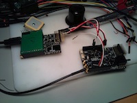
This was simply a process of balancing leads on the data pins of the working GPS and hooking them up to some of the servo signals on the other board (I love FPGAs 🙂 ). This worked as expected and I was able to talk to the GPS. However I was unable to get a position lock from it.
After pondering a while I gave a mate a call who I usually turn to in times of such technical conundrums. He was surprisingly quick to point out that I was using an active antenna but not actually supplying any power to it. It turns out I had completely missed the required inductor between VCC and the GPS’s RF line.
The datasheet for the GPS in question suggests a 33nH inductor is used to bias an active antenna. These are quite a lot smaller than the usual components found in labratory stock, and certainly not something found at the local electronics store. Being impatient, and unwilling to order a bunch of stuff to fill a shipment for a single inductor I decided to improvise.
After ‘jumpers’, inductors are the easiest component to manufacture yourself. They are just a coil of wire after all. Unfortunately it has been several years since my high school science teacher tried to teach me the maths involved in coiling an inductor. Luckily Google was more than willing to provide an ubundance of inductor calculators.
With some trial and error I picked some numbers that looked reasonable and wound some solder wire around a meter probe. After some more trial and error, I had a coil that was apparently in the right ball park.
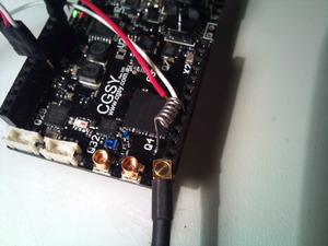
 With my home made inductor in place, I was amazed to find that I could actually track some satellites. I’ve managed to find 12 satellites while sitting Asity inside, on my desk. Amusingly they’re all to the northwest which is where my window happens to face.
So the GPS works fantastically (on half of my boards). The faults I have uncovered are not consistent for both boards, other than the missing inductor of course, so I’m still confident I can make this design work.

