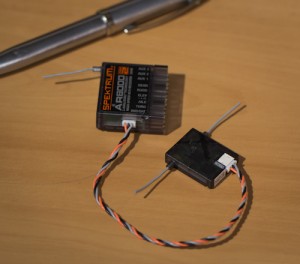
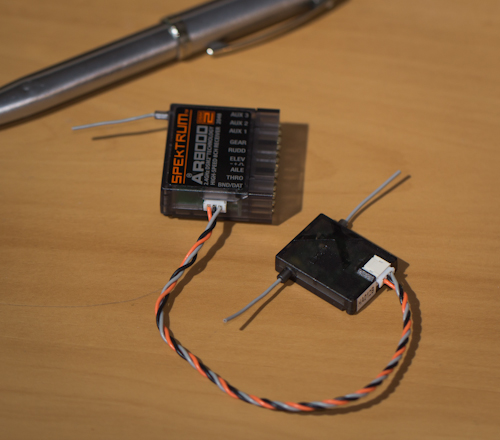
I’ve been playing around with my transmitter a lot recently as flying season is starting up again and the darn thing isn’t working well. Likewise, the receiver I’ve just installed in the Pulsar refuses to bind to my radio. So a big fail all round by Spektrum, which has lead me to seek alternative solutions.

I’ve seen a few forum threads discussing the serial protocol used by Spektrum’s remote receivers and it seems pretty straight forward to collect the data from them; bypassing the main receiver completely. Unfortunately the only decent write up of the details that I could find was a bit out of date, and only covered the 7 channel case. So here is what I’ve learnt from poking this device with an oscilloscope and a logic analyser for a few hours.
I’m using a Spektrum DX8 for all my testing and will focus on the DSMX modulation as that’s what made the most sense to me.
The physical layer is a very simple asynchronous serial stream. There are three wires: the orange is 3.3V, and will draw about 30mA, the black is ground, and the grey is serial data (3.3V).
The serial data is standard 115200 baud, 8 bit wide, no parity and one stop bit (8N1). I’ve seen many different reports on what this speed should actually be. My own measurements of the few receivers I have puts it around the 110 kbps mark. I’m pretty sure it’s ‘supposed’ to be 115.2K and you won’t have much trouble if you just use the standard speed.
Now things start to get a little tricky. My DX8 allows me to select either DSM2 or DSMX modulation as well as either an 11ms or 22ms frame speed. This seems to decide what resolution your data is (1024/2048) and will vary the packet format slightly. As far as I can tell, the DX8 always transmits packets 11ms apart, but as my main receiver won’t talk to me I can’t see the variations in the PWM output rate.
The data format is set when binding the receiver, and is stored along with the model data in the transmitter. You can bind multiple remote receivers, one at time as long as you have the same modulation and frame rate selected. I just use the AR8000 to bind the remote receivers and won’t look into binding without it.
Once powered up, the receiver will wait for the radio it is bound to, to begin transmitting. It will not send any data if it’s not receiving anything. This is also true if the transmitter is turned off, the remote receiver will simply stop sending data.
A frame consists of 16 bytes which includes 7 channels of data. If you are using more than 7 channels, which is the case for the DX8 then your frames will include two packets of 16 bytes, 11ms seconds apart.
Each data word is two bytes long (16 bits). The first word is a count of missed frames which uses at least 10 bits, I didn’t manage to get it to wrap around. The remaining seven words are channel data for the current stick positions.
The channel data is given in a seemingly random order, although during my testing it remained constant for a given modulation and frame speed even after power cycling and rebinding.
Each 16 bits contains the channel ID and the channel value, as well as a couple of zeros. Be aware that the channel ID bits did move when the receiver was bound using a 1024 mode versus a 2048 mode. The channel value is the 10 LSBs in a 1024 mode and the 11 LSBs in a 2048 mode. I believe DMS2 at 22ms is the only 1024 mode for this transmitter/receiver.
 The channel ID is the 3 or 4 bits above the channel value. I say 3 or 4 as I expect this protocol can handle more than 8 channels, but I have nothing to test that with. This identifies the channel to which the value following should be assigned. 0: Throttle, 1: Aileron, 2: Elevator, 3: Rudder, 4: Gear, 5: Aux1, 6: Aux2, 7: Aux3.
For DSMX, each channel will only be included once in each frame, so the spare words in each packet are set to all 1’s (0xFFFF). In DSM2-2048 A few channels were repeated in the second packet.
The MSB of each word appears to identify the packet within each frame. It is usually 0 except in the case where the word is not used for channel data (as above) or immediately following the Frame Loss Count in the second packet of the frame.
The channel values provide the duration of the pulse used to control the servos. The following is how I plan to implement my own PWM and not necessarily how the Spektrum receivers do it. It could be the same, I just can’t measure it while my receiver is broken.
 The DX8 allows servo travel to range from -150% up to 150%. A typical PWM controller will go from 1000us up to 2000us for the full range of the servo, so I’ve decided to go from 750us up to 2250us to match my transmitters range. You’ll find most of the scaling and direction of the data is done in the transmitter and only absolute positions are sent to the receiver.
There are a few details I didn’t really look into during the last few hours as I have enough to keep me going. So hopefully this is helpful to someone else and always remember that your mileage may vary.


Hi Ben,
Good work on this. I always wondered how the transmitter interfaced to the receiver. We, at Dickson College UAV, have moved to the DX8 and various Spektrum receivers with no issues on binding or anything else.
Glad to see your OBC work is progressing well. We are looking forward to seeing all of the approaches to the challenge.
Best regards,
Andrew
Thanks Andrew,
I managed to grab a DX8 from the first batch that was released, which had a few teething issues that have been ironed out in later releases.
O’Reilly Model Products have fixed my transmitter and replaced the receiver under warranty and they both seem to function fine. I do still have some issues with particular firmware versions though…
Fingers crossed I can get it off the ground in time for the D2 deadline!
Ben
Hi I pretty comprehensively decoded the DSM2 protocol and documented it in the comments to the code which can be found at:
http://paparazzi.github.com/docs/master/stm32_2subsystems_2radio__control_2spektrum__arch_8c_source.html
DSMX is not very much different.
Hi Eric,
How did you decode the protocol?
do you record data from data output of the main receiver or serial line between satellite and main receiver?
Thanx
Dead link above, new link is:
http://docs.paparazziuav.org/latest/stm32_2subsystems_2radio__control_2spektrum__arch_8c_source.html
Thanks for all the work 😉 We got our project to work thanks to it.
I think you have an error in your second picture the last two shorts of the frame should be 14 and 16 and not 16 and 18!
Glad I could help :).
You’re quite right about that error. Thanks for pointing it out.
Dear Ben,
I just found your blog. Very nice work. I thought YES I’ll find my answer here. But not, I’m not sure.
I have some issues with an OrangeRX module and receiver in 2048 mode. The servos are freezing sometime. I wonder if stock PPM values are right for that mode (22.5ms/300us/negative polarity)
What are the best value for the PPM port in 2048 mode?
Thank you